Input voltage control method

A technology of input voltage and control method, which is applied in the direction of AC motor control, electronic commutation motor control, control system, etc., can solve the problems of motor input voltage fluctuation, easy trigger current protection, and large volume of large electrolytic capacitors, etc., to achieve stable input The effect of voltage

Active Publication Date: 2021-07-30
JIANGSU DONGCHENG TOOLS TECH CO LTD
View PDF5 Cites 2 Cited by
  • Summary
  • Abstract
  • Description
  • Claims
  • Application Information

AI Technical Summary

Problems solved by technology

[0002] The existing AC brushless circuits all use large electrolytic capacitors, which make the motor control relatively simple, but the volume of large electrolytic capacitors is usually relatively large, which increases the volume of the circuit board. Therefore, the current conventional scheme adopts no large electrolytic capacitors, reducing Small size, and the circuit board has a long service life. However, since this circuit does not use large electrolytic capacitors and uses small-capacity capacitors, the bus voltage will change with the change of the load current after rectification. Usually, the controller needs to collect rectification After the voltage is controlled, the voltage input to the motor can be stabilized, but due to this change, the control effect of the brushless motor is affected, and due to the use of non-polar capacitors, the voltage fluctuation after rectification is easy to cause the input voltage supplied to the motor Fluctuation, and easy to trigger current protection

Method used


Image

  • Input voltage control method
  • Input voltage control method
  • Input voltage control method

Examples


Embodiment Construction

[0023] The present invention will be described in further detail below in conjunction with the accompanying drawings and embodiments.

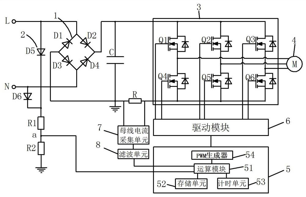
[0024] see figure 1 As shown, it is a motor control circuit related to the present invention, the motor control circuit includes an AC power supply, a first rectifier circuit 1 and a second Two rectification circuits 2, the output end of the first rectification circuit 1 is connected to the motor 4 through the drive circuit 3, the output end of the second rectification circuit 2 is connected to the controller 5, and the controller 5 is connected to the motor 4 through the drive module 6 The drive circuit 3 is used to drive the motor 4 to run.

[0025] The first rectification circuit 1 is a bridge-connected full-wave rectification circuit formed by connecting four rectification diodes D1, D2, D3, and D4 end-to-end. The anode of the AC power supply is connected to the cathode of the diode D1 and the anode of the diode D2, the anode of the diod...


PUM


Abstract

The invention discloses an input voltage control method, which comprises a power supply, a first rectifying circuit and a second rectifying circuit, the first rectifying circuit and the second rectifying circuit are connected in parallel between the positive electrode and the negative electrode of the power supply and rectify the power supply, the output end of the first rectifying circuit is connected to a motor through a driving circuit, and the output end of the second rectifying circuit is connected to a controller through a voltage detection circuit. The controller collects a bus voltage value U real and a bus current value, stores a target duty ratio value D target and a target voltage value U target, determines the corresponding target voltage value U target according to the collected bus current value, and obtains an output control duty ratio D real to drive the motor according to a formula: D real = (U target * D target)/U real. By collecting the output voltage of the second rectifying circuit, the waveform is stable, the control effect is good, the duty ratio is changed according to the bus voltage, and stable operation of the motor is improved.

Description

【Technical field】 [0001] The invention relates to the technical field of motor control, in particular to a method for controlling the input voltage of a brushless motor. 【Background technique】 [0002] The existing AC brushless circuits all use large electrolytic capacitors, which make the motor control relatively simple, but the volume of large electrolytic capacitors is usually relatively large, which increases the volume of the circuit board. Therefore, the current conventional scheme adopts no large electrolytic capacitors, reducing Small size, and the circuit board has a long service life. However, since this circuit does not use large electrolytic capacitors and uses small-capacity capacitors, the bus voltage will change with the change of the load current after rectification. Usually, the controller needs to collect rectification After the voltage is controlled, the voltage input to the motor can be stabilized, but due to this change, the control effect of the brushle...

Claims


Application Information

Patent Timeline
Patent Type & Authority Applications(China)
IPC IPC(8): H02P6/00H02P27/02
CPCH02P6/00H02P27/02H02P25/03H02P27/085H02P1/46H02P23/26H02P25/107
Inventor 黄佳楠
Owner JIANGSU DONGCHENG TOOLS TECH CO LTD
Why Eureka
Try Eureka