Metallurgy valve welding tool

A welding tool and valve technology, applied in welding equipment, auxiliary welding equipment, metal processing equipment, etc., can solve problems such as lack of positioning effect

Inactive Publication Date: 2021-08-03
南京旭涌机械科技有限公司
View PDF8 Cites 3 Cited by
  • Summary
  • Abstract
  • Description
  • Claims
  • Application Information

AI Technical Summary

Problems solved by technology

[0003] At present, when metallurgical valves are being processed, welding is one of the main processing procedures. In this process, welding tooling is required, but the existing welding tooling for metallurgical valve production does not have a good Positioning effect, therefore, it is urgent to set up a metallurgical valve welding tool to solve such problems

Method used


Image

  • Metallurgy valve welding tool
  • Metallurgy valve welding tool
  • Metallurgy valve welding tool

Examples


Embodiment 1

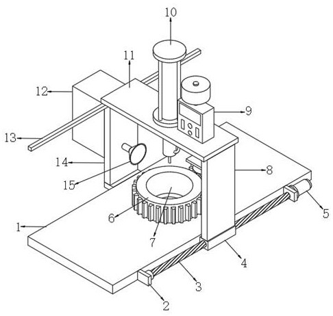
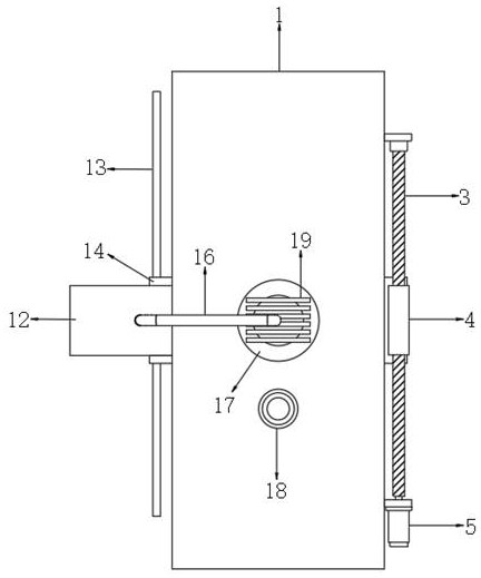
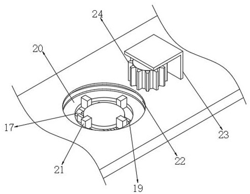
[0033] Metallurgical valve welding plant, such as Figure 1-6As shown, including a table 1, one side wall of the table 1 is connected to the forward mechanism through the bolt, and the top portion of the forward mechanism is connected to the support plate 8 through the bolt, and the top welding of the top plate 11 of the support plate 8, the top plate 11 The side is connected to the welding mechanism through the bolt, and the upper intermediate position of the table 1 is opened, and the positioning seat 6 is inserted inside the mounting groove 20, and the top intermediate position of the positioning seat 6 opens a positioning groove 7, the positioning groove 7 The intermediate position of the bottom inner wall is connected to the suction barrier 27 by bolts, and both sides of the positioning groove 7 have a vertical groove 25, and the vertical groove 25 is rotated between the opposite side inner walls of the top by a pin shaft. 29 The bottom side of the movable frame 29 is welded w...

Embodiment 2

[0043] Metallurgical valve welding plant, such as Figure 7 As shown, in order to solve the problem of adsorption of metal scraps of the welding process being suction block 27; the present embodiment, the following improvements are made based on the first embodiment: replace the first heat sink 19 and the second heat sink 37. The heat absorbing plate 41 is opened on both sides of the top of the positioning seat 6, and the heat absorbing plate 41 is engaged inside the groove.

[0044] When the embodiment is used, the user replaces the first heat sink 19 and the second heat sink 37 by the heat absorbing plate 41. When the gas is discharged into the welding through the exhaust pipe 16, the welding process can be absorbed by the heat absorbing plate 41. The heat generated by the arc, the heat of the welding, and the heat in the gas such that the top of the positioning seat 6 produces a certain high temperature, using high temperature eliminating the magnetic force to the top of the pos...


PUM


Abstract

The invention discloses a metallurgical valve welding tool. The welding tool comprises a workbench, an advancing mechanism is fixedly connected to the outer wall of one side of the workbench, a supporting plate is fixedly connected to the top of the advancing mechanism, a top plate is fixedly connected to the top of the supporting plate, and a welding mechanism is fixedly connected to one side of the top of the top plate; and a mounting groove is formed in the middle of the top of the workbench, a positioning seat is inserted into the mounting groove, a positioning groove is formed in the middle of the top of the positioning seat, an iron attraction block is fixedly connected to the middle of the inner wall of the bottom of the positioning groove, and vertical grooves are formed at the two sides of the positioning groove. According to the metallurgical valve welding tool, metallurgical valves of different diameters can be conveniently positioned, metallurgical valves in various shapes can be positioned, ventilation cooling treatment can be conducted on the interior of the positioning groove and the welding position, welding scraps can be prevented from being attracted to the iron attraction block due to the action of magnetic force, and the welding scraps are effectively prevented from influencing the positioning function of a metallurgical valve.

Description

Technical field [0001] The present invention relates to the field of metallurgical valve, in particular, to a metallurgical valve welding plant. Background technique [0002] The valve is a control component in a pipe fluid delivery system to change the direction of the passage and the medium flow direction, with a stream, cutoff, throttling, check, shunt, or overflow unloading. Valves for fluid control, from the simplest shutoff valve to various valves used in extremely complex self-control systems, variety of varieties and specifications can be used, such as manual, electric, hydraulic, pneumatic, electromagnetic Moving, positive gears, umbrella gears, etc. [0003] At present, when the metallurgical valve is processed, the welding is one of its main processing processes. In this process, it is necessary to utilize the welding tool, but the existing metallurgical valve production welding tool is not used, does not have good The positioning effect, therefore, there is an urgent ...

Claims


Application Information

Patent Timeline
Patent Type & Authority Applications(China)
IPC IPC(8): B23K37/04B23K37/00
CPCB23K37/003B23K37/0443B23K37/00
Inventor 许仙佑
Owner 南京旭涌机械科技有限公司
Why Eureka
Try Eureka