
Reciprocating motion device

A technology of reciprocating motion and motion, applied in the field of reciprocating motion devices, can solve the problems of time-consuming and laborious design, low accuracy and low precision, and achieve the effects of simple structure, high accuracy and convenient operation.

Pending Publication Date: 2021-08-03
NANJING LINGJI YIDONG DRIVING TECH CO LTD
View PDF1 Cites 0 Cited by
  • Summary
  • Abstract
  • Description
  • Claims
  • Application Information

AI Technical Summary

Problems solved by technology

[0003] Punching is a common process, and the depth and accuracy of the punching position are very high on some precision instruments or equipment, but the existing punching equipment has the defects of low efficiency and low accuracy, and at the same time Manual drilling is time-consuming and labor-intensive, so it is urgent to develop a device with high drilling efficiency, high accuracy, and time-saving and labor-saving
[0004] Patent document CN 208584621U discloses a hand-operated hole puncher, which includes a support frame, a vertical shaft assembly, and a drive mechanism; the vertical shaft assembly is installed on the support frame and passes through the support frame to complete axial movement, and the drive mechanism is installed on the support frame On the frame and in contact with the vertical shaft assembly, it drives the corresponding components of the vertical shaft assembly; by operating the driving mechanism, the rotational motion of the driving mechanism is converted into the vertical shaft assembly’s up and down reciprocating motion; the vertical shaft assembly generates the impact force of the reciprocating motion, and The corresponding components of the support part cooperate to punch holes in the article, but this design is time-consuming and laborious and the accuracy is not high

Method used


Image

  • Reciprocating motion device
  • Reciprocating motion device
  • Reciprocating motion device

Examples


Embodiment Construction

[0062] The present invention will be described in detail below in conjunction with specific embodiments. The following examples will help those skilled in the art to further understand the present invention, but do not limit the present invention in any form. It should be noted that those skilled in the art can make several changes and improvements without departing from the concept of the present invention. These all belong to the protection scope of the present invention.

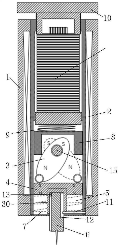
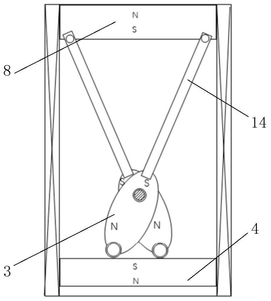
[0063] The invention provides a reciprocating device, such as figure 1As shown, it includes a housing 1, a drive assembly and a functional assembly. The housing 1 is provided with an electromagnet 2. The electromagnet 2 is preferably an electromagnetic coil. The drive assembly is provided with a permanent magnet structure 3. The permanent magnet structure 3 is preferably a The permanent magnet, when the electromagnet 2 is energized, can generate a magnetic field and the magnetic force of the magnetic fi...


PUM


Abstract

The invention provides a reciprocating motion device which comprises a shell, a driving assembly and a functional assembly. An electromagnet is arranged on the shell. When the electromagnet is powered on, the driving assembly can be driven to move so as to enable the functional assembly to move from a first position to a second position. When the electromagnet is powered off, the driving assembly can be driven by the driving assembly to move so as to enable the functional assembly to move from the second position to the first position. Or the functional assembly can be driven by the functional assembly to move from the second position to the first position, the first position is the initial position, and the second position is the target position. In the reciprocating motion device, the electromagnet is used for generating a magnetic field, the reciprocating impact action of a functional head of the reciprocating motion device is achieved through magnetic force, accuracy is high, and the speed is high; and compared with an existing automatic reciprocating motion device, the reciprocating motion device has the advantages of being simpler in structure, time-saving, labor-saving and high in accuracy and is beneficial to application and popularization.

Description

technical field [0001] The invention relates to the technical field of mechanical structures, in particular to a reciprocating device. Background technique [0002] In mechanical motion, reciprocating motion is a very common type of motion, which can achieve multiple functions, such as drilling, cutting, grinding, workpiece transfer, etc. A series of operations involve reciprocating motion, even in medical equipment. involves. [0003] Punching is a common process, and the depth and accuracy of the punching position are very high on some precision instruments or equipment, but the existing punching equipment has the defects of low efficiency and low accuracy, and at the same time Manual punching is time-consuming and labor-intensive, so it is urgent to develop a device with high punching efficiency, high accuracy, and time-saving and labor-saving. [0004] Patent document CN 208584621U discloses a hand-operated hole puncher, which includes a support frame, a vertical shaft...

Claims


Application Information

Patent Timeline
Patent Type & Authority Applications(China)
IPC IPC(8): B26F1/02B26D5/08B26D7/01
CPCB26F1/02B26D5/086B26D7/01
Inventor 杨斌堂
Owner NANJING LINGJI YIDONG DRIVING TECH CO LTD
Learn More