
A new type of floating wind turbine platform

A floating and fan technology, which is applied to wind turbines, wind turbine control, installation/support configuration of wind turbines, etc., can solve problems such as the inability to meet the fast and stable platform, narrow application range, slow response speed, etc., and achieve a simple structure. , Wide range of applications, the effect of reducing the load

Active Publication Date: 2022-06-28
CSIC CHONGQING HAIZHUANG WINDPOWER EQUIP +1
View PDF0 Cites 0 Cited by
  • Summary
  • Abstract
  • Description
  • Claims
  • Application Information

AI Technical Summary

Problems solved by technology

[0004] Aiming at the deficiencies of the existing technology, the present invention proposes a new type of floating fan platform to solve the problem that the existing platform proposed in the above background technology is stable, but the response speed of the ballast is slow, which cannot meet the needs of a fast and stable platform. , and when the existing platform is ballasted in order to maintain stability, it will inevitably be accompanied by an increase in the draft of the platform, which is not suitable for waters that require water depth, and the applicable range is narrow

Method used


Image

  • A new type of floating wind turbine platform
  • A new type of floating wind turbine platform
  • A new type of floating wind turbine platform

Examples


Embodiment Construction

[0033] Embodiments of the technical solutions of the present invention will be described in detail below with reference to the accompanying drawings. The following examples are only used to more clearly illustrate the technical solutions of the present invention, and are therefore only used as examples, and cannot be used to limit the protection scope of the present invention.

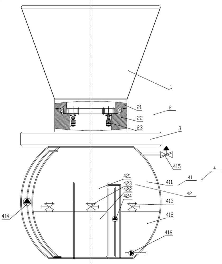
[0034] see figure 1 , The novel floating fan platform provided in this embodiment includes a buoy 1, a transition section 2, a heave plate 3 and a ballast tank system 4 connected in sequence.

[0035] A fan is installed on the end face of the buoy 1 away from the transition section 2 . Specifically, the buoy 1 is tapered, and the taper range is 15-20 degrees. The conical buoy 1 can effectively reduce the movement of the platform, make the platform more stable, and increase the restoring moment.

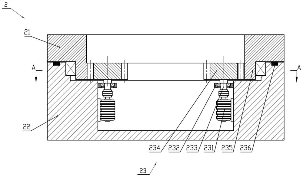
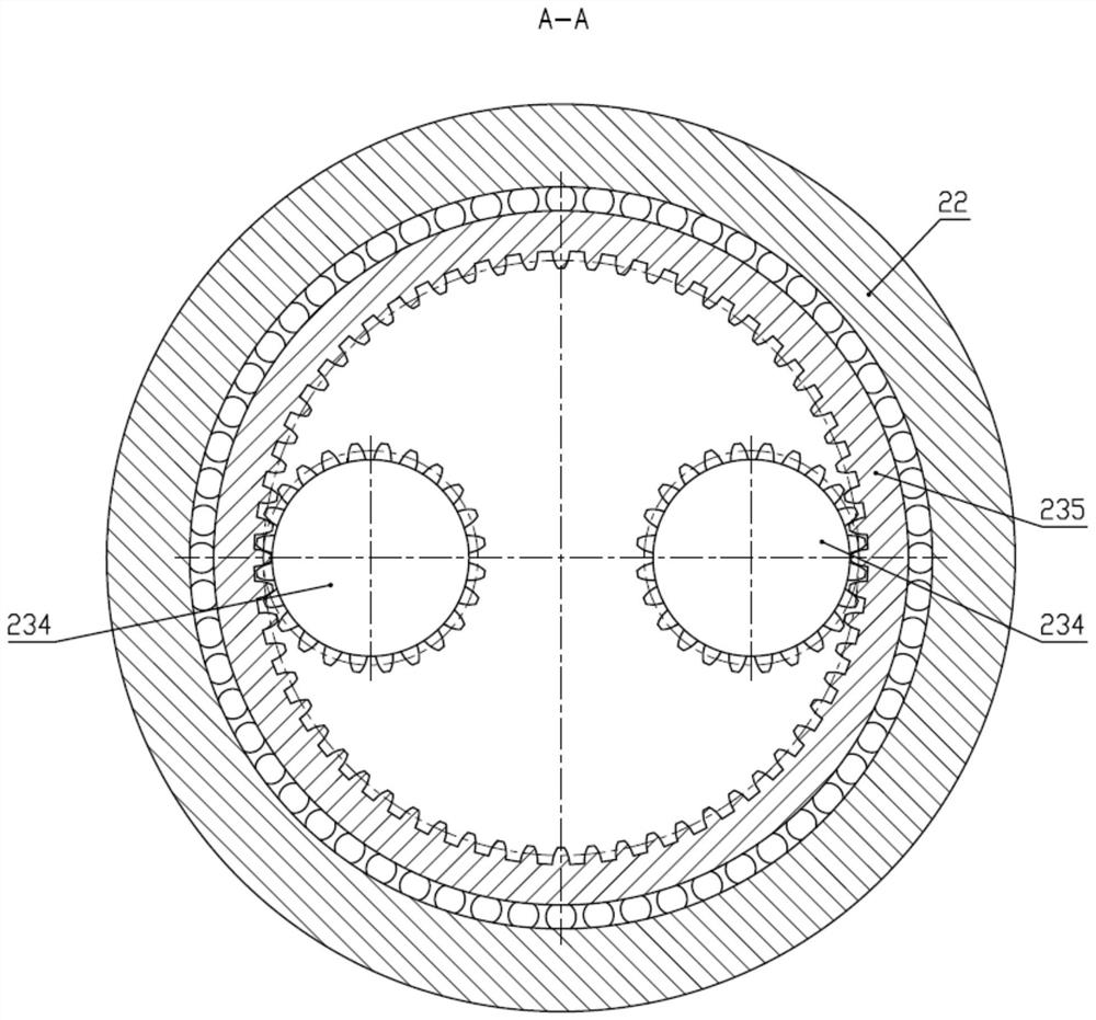
[0036] Please also refer to figure 2, the cross section of the transition section 2 is smaller than th...


PUM


Abstract

The invention discloses a novel floating fan platform, which comprises a buoy, a transition section, a heave plate and a ballast tank system connected in sequence; a fan is installed on the end surface of the buoy away from the transition section; the cross section of the transition section is smaller than any of the buoys. The height of the cross section; the cross section of the heave plate is larger than that of the fixed seat; the ballast tank system includes spherical ballast tanks and mercury ballast tanks, the top of the spherical ballast tank is fixedly connected with the heave plate, and the spherical ballast tank The position of the center of gravity of the spherical ballast tank is changed by changing the position of the internal water to adjust the stability of the platform. The mercury ballast tank is located in the spherical ballast tank. The mercury ballast tank changes the mercury pressure by changing the position of the internal mercury. The position of the center of gravity of the loading compartment thus adjusts the stability of the platform. The above-mentioned solution has a fast response speed and meets the needs of the platform for fast and stable performance. Since the draft remains unchanged, it is suitable for water areas that require water depth and has a wide range of applications.

Description

technical field [0001] The invention relates to the technical field of marine floating fan platforms, in particular to a novel floating fan platform. Background technique [0002] As an emerging hotspot in renewable energy research, deep-sea wind power generation has great potential because, compared with onshore wind power, deep-sea wind power generation has a more uniform wind speed due to lower sea surface roughness than land surface; followed by deep-sea wind power generation The wind speed is higher in the sea, which makes it possible to obtain more wind energy, and finally has less impact on the environment and more wind farms can be used. For floating wind power equipment, the entire equipment includes: wind turbines, floating platforms, mooring systems and anchoring systems. As the most important component, the floating platform is characterized by motion with 6 degrees of freedom, and is subjected to large shock loads from the environment, such as waves, wind, ice ...

Claims


Application Information

Patent Timeline
Patent Type & Authority Patents(China)
IPC IPC(8): B63B35/44B63B11/04B63B13/00F03D13/25F03D7/04
CPCB63B35/44B63B11/04B63B13/00F03D13/25F03D7/0204B63B2035/446Y02E10/727
Inventor 周舒旎董晔弘王叶倪远翔杨林陶治宇仵文松李成周闯蒋运和
Owner CSIC CHONGQING HAIZHUANG WINDPOWER EQUIP
Learn More