Air pressure pushing and vibrating device

A vibration device and air pressure technology, which is applied in construction, sheet pile walls, foundation structure engineering, etc., can solve problems such as belt cages, steel cages floating up, concrete not filling, etc.

Pending Publication Date: 2021-08-03
陈清贵
View PDF0 Cites 0 Cited by
  • Summary
  • Abstract
  • Description
  • Claims
  • Application Information

AI Technical Summary

Problems solved by technology

[0004] When the pipe is pulled out, the steel cage will float up, resulting in a cage; the concrete will block the steel pipe; after the concrete is poured, the concrete will not be filled and compact; during the pipe pulling process, the concrete will be squeezed by the retractive force of the soil around the steel pipe, resulting in necking

Method used


Image

  • Air pressure pushing and vibrating device
  • Air pressure pushing and vibrating device
  • Air pressure pushing and vibrating device

Examples


Embodiment Construction

[0024] The present invention will be described in detail below in conjunction with the accompanying drawings and specific embodiments.

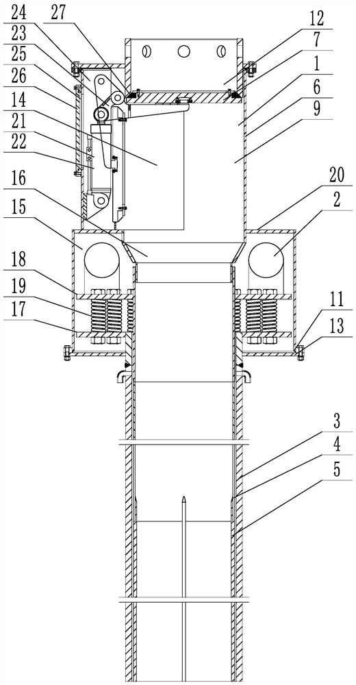
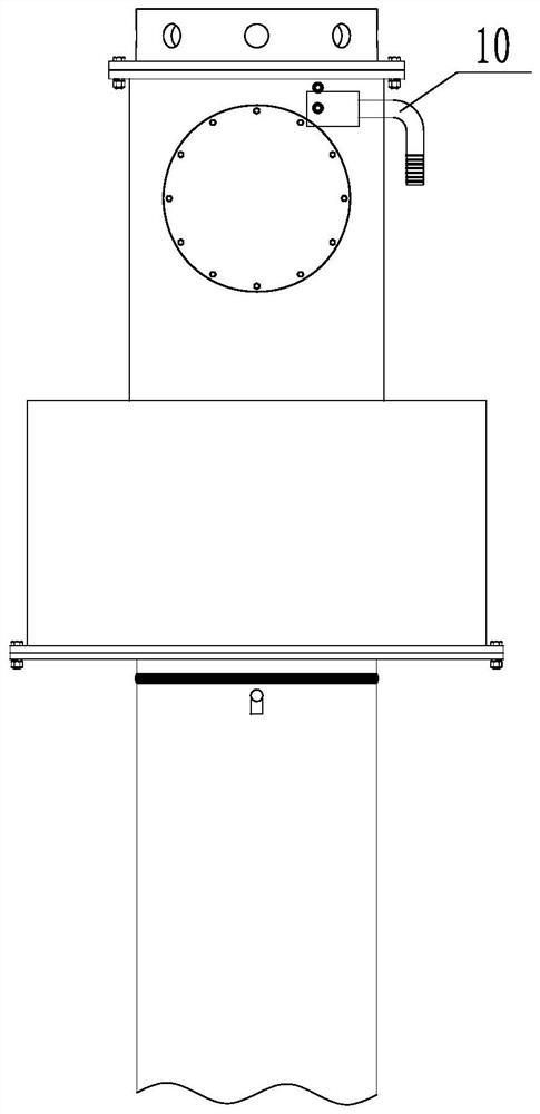
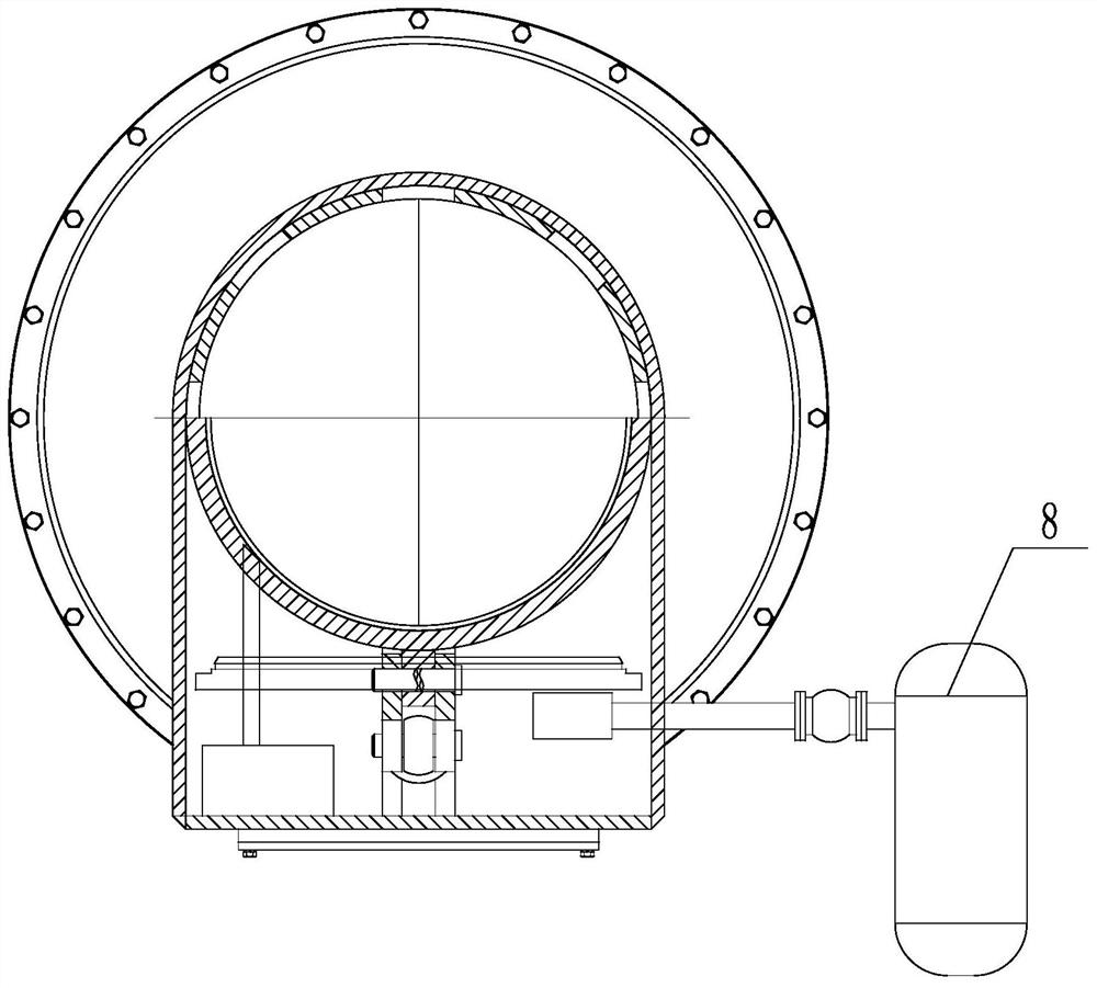
[0025] The present invention relates to a pneumatic pushing and vibrating device, such as figure 1 , figure 2 , image 3 , Figure 4 As shown, it includes an air pressure sealing device 1, a vibration device 2, an outer tube 3, an inner tube 4, and a steel brazing rod 5; the air pressure sealing device 1 includes a valve body 6, a cover plate 7, and a booster mechanism 8. A valve cavity 9 is formed in the valve cavity 9, and an air inlet 10 is opened in the valve cavity 9, and the air inlet 10 leads to a booster mechanism 8, and the booster mechanism 8 is any existing device capable of providing high-pressure gas , an outer pipe interface 11 is provided below the valve cavity 9, and the outer pipe interface 11 is sealed and connected to the outer pipe 3. During construction, the outer pipe 3 is pushed downward to the pile tip by using a s...


PUM


Abstract

The invention discloses an air pressure pushing and vibrating device. The air pressure pushing and vibrating device comprises an air pressure sealing device, a vibrating device, an outer pipe, an inner pipe and steel chisels. The air pressure sealing device comprises a valve body, a cover plate and a pressurizing mechanism, a valve cavity is formed in the valve body, an air inlet channel is formed in the valve cavity, the air inlet channel communicates with the pressurizing mechanism, an outer pipe connector is formed in the lower part of the valve cavity, an outer pipe is hermetically connected to the lower part of the outer pipe connector, a feeding port is formed in the upper part of the valve cavity, and the cover plate is arranged at the feeding port and seals or opens the feeding port. The vibrating device is arranged in the valve cavity, the inner pipe is inserted into the outer pipe, a gap is formed between the inner pipe and the outer pipe, the multiple steel chisels are annularly arranged on the lower side of the inner pipe along the pipe wall and extend downwards, the vibrating device is fixed above the inner pipe, and the inner pipe and the outer pipe are elastically connected at the upper end of the outer pipe. The concrete is more full and compact during pipe sinking and pouring, the steel pipe is prevented from hanging a reinforcement cage during pipe drawing, the steel pipe is prevented from being blocked by the concrete, and meanwhile necking is prevented.

Description

technical field [0001] The invention relates to the technical field of immersed pipe grouting piles, in particular to an air pressure pushing and vibrating device. Background technique [0002] Immersed tube cast-in-place pile is a commonly used pile foundation construction method at present. Compared with prefabricated pile, immersed tube cast-in-situ pile is more corrosion-resistant in corrosive soil layers; compared with bored cast-in-place pile, it avoids floating soil at the pile tip The resulting pile body sinks, insufficient holding force and other problems. During the construction of this method, the steel pipe corresponding to the design size of the pile foundation is used to press the pile tip downward, the steel pipe and the pile tip are sunk into the soil layer, a steel cage is placed in the steel pipe, and then concrete is poured into the steel pipe, and at the same time, it is vibrated or hammered. Out of the steel pipe. [0003] However, the existing immerse...

Claims


Application Information

Patent Timeline
Patent Type & Authority Applications(China)
IPC IPC(8): E02D5/38E02D15/04
CPCE02D5/38E02D15/04
Inventor 陈清贵
Owner 陈清贵
Why Eureka
Try Eureka