Turbine compounding system with multi-stage energy utilization function, and control method

A technology of turbocombination and control method, which is applied in the direction of electrical control, engine control, fuel injection control, etc., and can solve the problem that the exhaust energy of the engine cannot be recovered effectively, the high-speed working condition and the low-speed working condition cannot be considered, and the exhaust gas energy cannot Reasonable utilization and other issues are beneficial to the increase of air intake, solving the slow dynamic response at low speed, and improving the low-speed responsiveness

Inactive Publication Date: 2021-08-03
DONGFENG COMML VEHICLE CO LTD
View PDF10 Cites 2 Cited by
  • Summary
  • Abstract
  • Description
  • Claims
  • Application Information

AI Technical Summary

Problems solved by technology

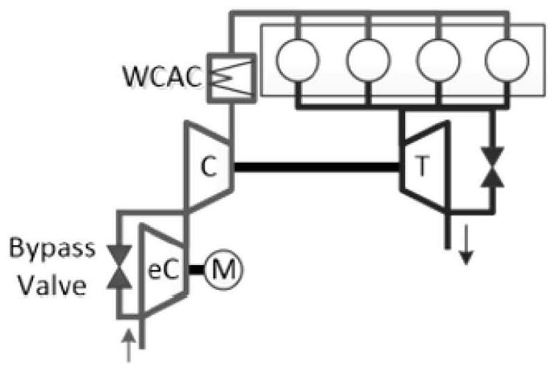
This system does not involve electric supercharging, and cannot achieve turbo compounding to effectively recover the exhaust energy of the engine
[0011] Another example is patent CN104329148B, which provides a two-stage power turbine system, including an internal combustion engine body, an intake manifold, an exhaust manifold, a turbocharger, a low-pressure power turbine, and a mechanical transmission. The turbocharger It includes a supercharging turbine and a compressor, the inlet of the supercharging turbine is connected to the exhaust manifold, the outlet of the supercharging turbine is connected to the inlet of the low-pressure power turbine, and a high-pressure power turbine is also included. The high-pressure power turbine is coaxially connected with the low-pressure power turbine, the air inlet of the high-pressure power turbine is connected with the exhaust manifold through a bypass pipeline, and the gas outlet of the high-pressure power turbine is connected with the gas outlet of the low-pressure power turbine through After the pipes are connected in parallel, they are then connected to the exhaust manifold. Similarly, this system does not involve electric supercharging, and cannot achieve turbo compounding to effectively recover the exhaust energy of the engine.
[0012] In summary, the single turbocharger commonly used in the prior art usually cannot take into account both high-speed and low-speed conditions, and most of the exhaust gas energy cannot be used reasonably

Method used


Image

  • Turbine compounding system with multi-stage energy utilization function, and control method
  • Turbine compounding system with multi-stage energy utilization function, and control method
  • Turbine compounding system with multi-stage energy utilization function, and control method

Examples


Embodiment Construction

[0044] The technical solutions of the present invention will be clearly and completely described below in conjunction with the accompanying drawings. Apparently, the described embodiments are some of the embodiments of the present invention, but not all of them. Based on the embodiments of the present invention, all other embodiments obtained by persons of ordinary skill in the art without making creative efforts belong to the protection scope of the present invention.

[0045] In the description of the present invention, it should be noted that unless otherwise specified and limited, the terms "installation", "connection" and "connection" should be understood in a broad sense, for example, it can be a fixed connection or a detachable connection. Connected, or integrally connected; it may be mechanically connected or electrically connected; it may be directly connected or indirectly connected through an intermediary, and it may be the internal communication of two components. ...


PUM


Abstract

The invention discloses a turbine compounding system with a multi-stage energy utilization function, and a control method. The turbine compounding system comprises an air compressor and an electric air compressor which are connected in series, and an outlet of the electric air compressor is connected with an inlet of an intercooler; an outlet of the intercooler is connected with a gas inlet of an engine, and a gas outlet of the engine is connected with an inlet of a turbocharger; an outlet of the turbocharger is connected with the input end of a power turbine; the output end of the power turbine is connected with a motor or a generator; a valve P1 is arranged on a pipeline connected between an inlet and an outlet of the air compressor, and a valve P2 is arranged on a pipeline connected between an inlet and an outlet of the electric air compressor; and a bypass valve is arranged on a pipeline connected between an inlet and an outlet of the turbocharger. The advantages of the turbine compounding system and an electric supercharging system are integrated, and turbine compounding can be achieved so that exhaust energy of the engine can be effectively recycled; electric supercharging can be achieved, the low-speed responsiveness can be improved, and the air inflow of the whole engine can be improved.

Description

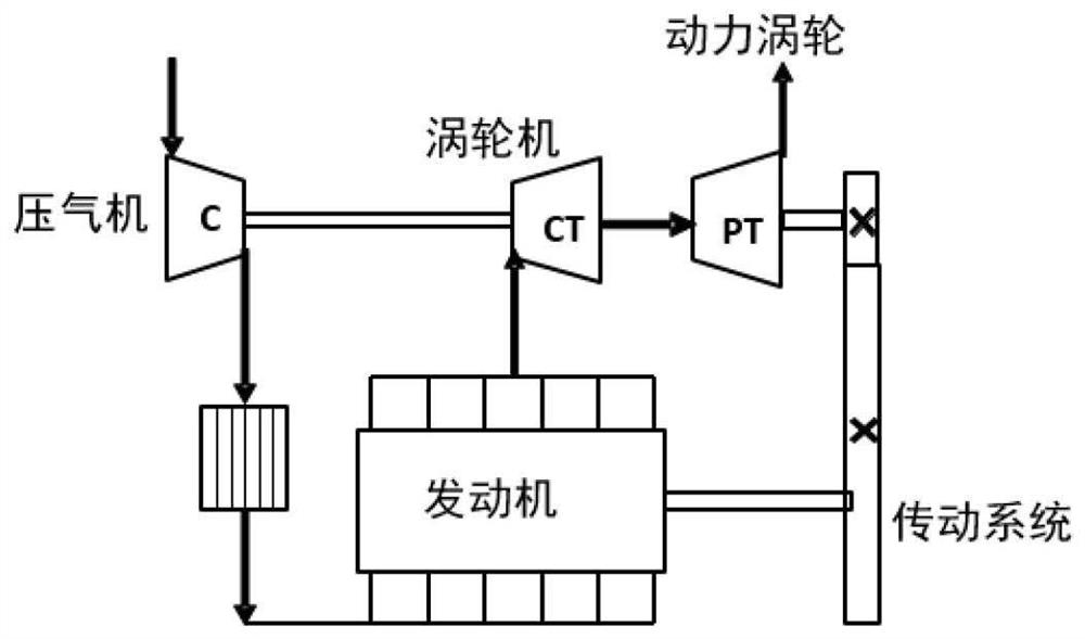
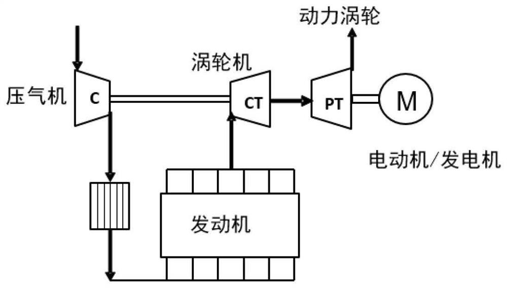
technical field [0001] The invention belongs to the technical field of engines, and in particular relates to a turbo compound system with multi-stage energy utilization and a control method. Background technique [0002] The turbo compound system is one of the waste heat recovery technologies of the engine, and it is also one of the important technical means to realize the energy saving and emission reduction of the engine. It absorbs and utilizes the heat in the exhaust gas through the power turbine and converts it into the rotational kinetic energy of the turbine, and then inputs the energy through the transmission system. into the engine crankshaft, so as to increase the engine power output and improve the energy utilization rate of the engine. The structure is as follows figure 1 shown. Or convert the waste heat energy absorbed by the power turbine into the energy of the motor for storage, and play the role of turbine power generation, such as figure 2 shown. [0003...

Claims


Application Information

Patent Timeline
Patent Type & Authority Applications(China)
IPC IPC(8): F02B37/04F02B37/10F02B37/12F02B37/22F02B39/10F02D41/00F02D45/00
CPCF02B37/04F02B37/10F02B39/10F02B37/12F02B37/22F02D45/00F02D41/0007Y02T10/12
Inventor 米娇赵艳婷殷勇李平
Owner DONGFENG COMML VEHICLE CO LTD
Why Eureka
Try Eureka