
Air inlet flow guide device and combined stove

A technology of a diversion device and a combined stove, which is applied in the directions of household stoves, household stoves/stoves, household heating, etc., can solve problems such as water conduction and water conduction which cannot be effective and drip into the volute of the fan assembly below. , to achieve the effect of improving the air intake effect, improving the air intake state and improving the work efficiency

Pending Publication Date: 2021-01-22
FOSHAN SHUNDE MIDEA WASHING APPLIANCES MFG CO LTD
View PDF7 Cites 0 Cited by
  • Summary
  • Abstract
  • Description
  • Claims
  • Application Information

AI Technical Summary

Problems solved by technology

For the combination cooker system with the fan in the middle, the air inlet of the fan and the air inlet of the volute are directly arranged, and the combination cooker with the fan in the middle, because the air flow rate at the air inlet is very high, the condensation condensed on the filter at the air inlet In addition to the effect of gravity, water also bears the obvious suction effect of the fan assembly of the combined stove. Therefore, if the filter screen structure of conventional multi-layer aluminum mesh is used, even if the filter screen is arranged obliquely, it cannot effectively guide water, and the condensed water will still drip through the filter and into the volute of the fan assembly below

Method used


Image

  • Air inlet flow guide device and combined stove
  • Air inlet flow guide device and combined stove
  • Air inlet flow guide device and combined stove

Examples


Embodiment Construction

[0042] Embodiments of the present invention are described in detail below, examples of which are shown in the drawings, wherein the same or similar reference numerals designate the same or similar elements or elements having the same or similar functions throughout. The embodiments described below by referring to the figures are exemplary only for explaining the present invention and should not be construed as limiting the present invention.

[0043] In the description of the present invention, it should be understood that the orientation descriptions, such as up, down, front, back, left, right, etc. indicated orientations or positional relationships are based on the orientations or positional relationships shown in the drawings, and are only In order to facilitate the description of the present invention and simplify the description, it does not indicate or imply that the device or element referred to must have a specific orientation, be constructed and operated in a specific ...


PUM


Abstract

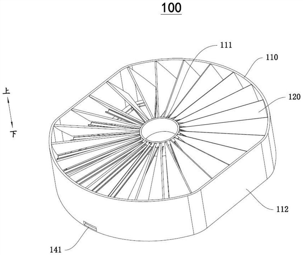
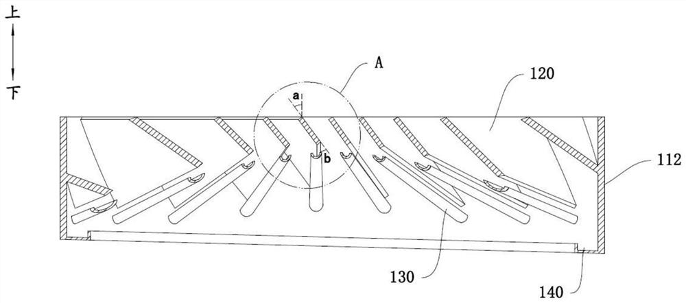
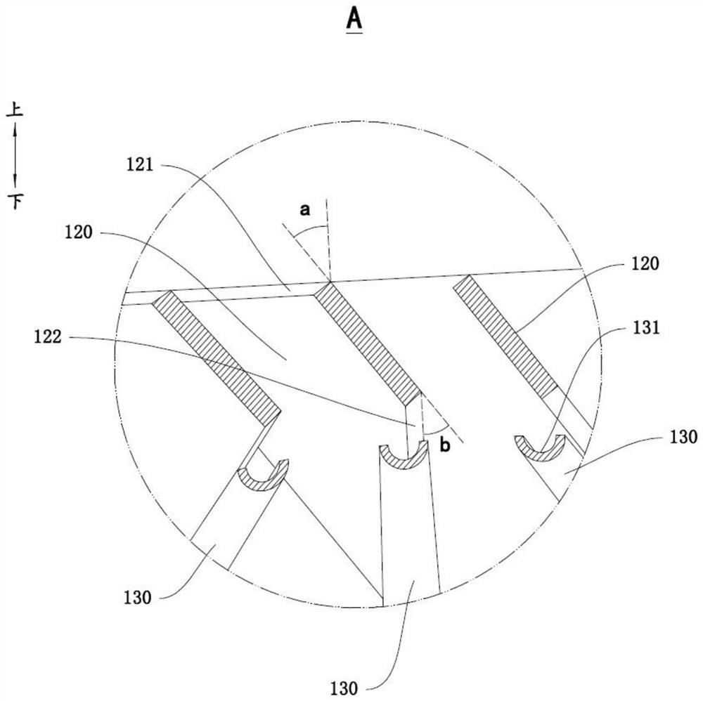
The invention discloses an air inlet flow guide device and a combined stove. The air inlet flow guide device comprises a fixing frame, a plurality of flow guide pieces and a plurality of water guide pieces, wherein the plurality of flow guide pieces are vertically and obliquely arranged on the fixing frame at intervals in the circumferential direction, the water guide pieces are in one-to-one correspondence with the flow guide pieces, the water guide pieces are arranged below the flow guide pieces, and the water guide pieces are provided with water grooves. During air inlet, airflow penetratesthrough gaps between the adjacent flow guide pieces and impacts the flow guide pieces, and water vapor in the airflow is condensed on the flow guide pieces to form condensate water; due to the fact that the flow guide pieces are vertically and obliquely arranged on the fixing frame, under the action of gravity and suction force of a fan assembly, the condensate water drips downwards into the water grooves of the water guide pieces below the flow guide pieces along the flow guide pieces and is guided out of the outside, so that the condensate water is effectively prevented from dripping to thefan assembly; and meanwhile, due to the fact that the flow guide pieces are vertically and obliquely arranged on the fixing frame, after the airflow is guided out through the flow guide pieces, the airflow forms pre-rotation, the air inlet state of the fan assembly can be improved, and the air inlet effect is improved.

Description

technical field [0001] The invention relates to the technical field of household appliances, in particular to an air inlet guide device and a combined cooker. Background technique [0002] In related technologies, combination cookers are more and more widely used in modern kitchens. Combination cookers are usually equipped with fans, and some combination cookers arrange fans under the plane of the cooktop. Discharge from the bottom of the table. The combination cooker is usually equipped with a filter screen, and the filter screen is installed near the air inlet of the combination cooker. For the combination cooker system with the fan in the middle, the air inlet of the fan and the air inlet of the volute are directly arranged, and the combination cooker with the fan in the middle, because the air flow rate at the air inlet is very high, the condensation condensed on the filter at the air inlet In addition to the effect of gravity, water also bears the obvious suction effe...

Claims


Application Information

Patent Timeline
Patent Type & Authority Applications(China)
IPC IPC(8): F24C15/20
CPCF24C15/2028F24C15/2035F24C15/2042
Inventor 李佳阳
Owner FOSHAN SHUNDE MIDEA WASHING APPLIANCES MFG CO LTD
Learn More