Staggered centrifugal impeller with asymmetrically distributed blades

A centrifugal impeller, asymmetric technology, applied in non-variable-capacity pumps, components of pumping devices for elastic fluids, machines/engines, etc., to suppress static and dynamic interference, avoid excitation superposition effects, and reduce flow-induced noise energy effect

Pending Publication Date: 2021-08-03
JIANGSU UNIV
View PDF2 Cites 0 Cited by
  • Summary
  • Abstract
  • Description
  • Claims
  • Application Information

AI Technical Summary

Problems solved by technology

At present, there is no patent report on the reduction of noise due to the

Method used


Image

  • Staggered centrifugal impeller with asymmetrically distributed blades
  • Staggered centrifugal impeller with asymmetrically distributed blades
  • Staggered centrifugal impeller with asymmetrically distributed blades

Examples


Embodiment Construction

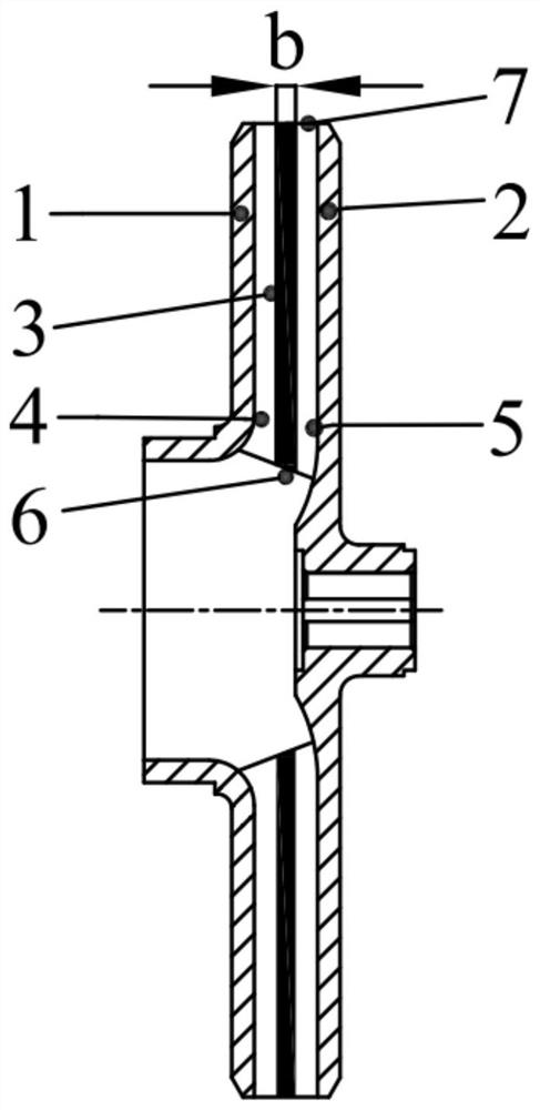
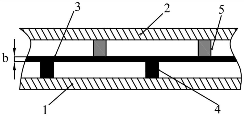
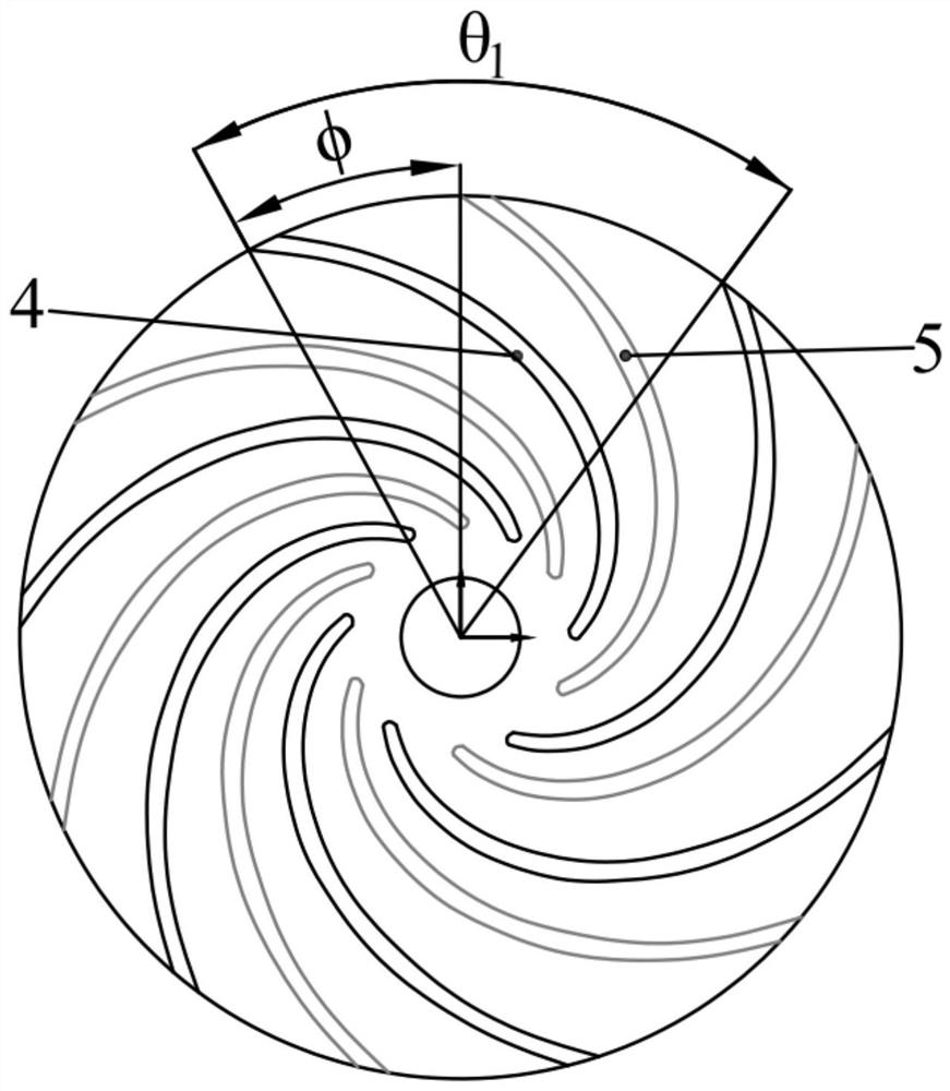
[0010] Such as figure 1 As shown, the middle rib 3 is located between the front cover plate 1 and the rear cover plate 2 of the impeller, and is in the center of the impeller flow channel. It starts from the blade inlet edge 6 and ends at the blade outlet edge 7, and divides the blade into independent The front half blade 4 and the rear half blade 5 are located at both sides of the middle rib 3 . When the number of middle ribs is 2-3, the impeller is divided into 2-4 layers. Such as figure 2 As shown, in this solution, the average thickness δ of the blade is 5 mm, and the thickness b of the middle rib 4 is 3 mm, which is 60% of the average thickness of the blade. Depend on image 3 It can be seen that the number of impeller blades in this scheme is 6, the front half blade 4 and the second half blade 5 are staggered after rotation, and the angle φ between them is 30°. The front half blades 4 and the second half blades 5 are arranged asymmetrically with the same rules along...


PUM


Abstract

The invention relates to a staggered centrifugal impeller with asymmetrically distributed blades. According to the staggered centrifugal impeller, the blades are divided into two independent parts through a rib plate, the two parts of the blades are rotated to form a specific angle, the uniformity of an outlet flow field of the impeller is improved, and the dynamic and static interference effect of the impeller and a pumping chamber is restrained. Meanwhile, a front half blade and a rear half blade are asymmetrically arranged according to a certain rule to form the unique staggered centrifugal pump impeller with the asymmetrically distributed blades. The structure reconstructs the internal flow rule of the impeller, inhibits the dynamic and static interference effect of the impeller and the pumping chamber, avoids the excitation superposition effect generated by symmetrical and uniform arrangement of the blades, and reduces the flow-induced noise energy, and therefore achieves the purpose of low-noise centrifugal pump design.

Description

technical field [0001] The invention relates to a staggered centrifugal impeller with asymmetrically distributed blades. The patent of the invention and the related design method can be applied in the field of centrifugal pumps, mixed flow pumps, centrifugal pump fans, mixed flow fans, axial flow fans and other blade impellers. fluid machinery field. Background technique [0002] As an important energy conversion device and fluid conveying equipment, pumps are widely used in various sectors of the national economy and cutting-edge technical fields such as ships and aerospace, of which centrifugal pumps account for about 70%. The noise generated by the pump has become one of the main noise sources in factories, pumping stations and residential quarters. Especially in the fields of industry, nuclear power and military equipment, the vibration and noise level of the pump has become an important performance indicator. The noise generated by the pump is mainly divided into two t...

Claims


Application Information

Patent Timeline
IPC IPC(8): F04D29/22F04D29/24F04D29/28F04D29/30F04D29/66
CPCF04D29/2238F04D29/245F04D29/28F04D29/30F04D29/666F04D29/667F04D29/669
Inventor 顾嘉嵘高波张宁倪丹
Owner JIANGSU UNIV
Why Eureka
Try Eureka