Eureka AIR delivers breakthrough ideas for toughest innovation challenges, trusted by R&D personnel around the world.

Studio centralized control system

A centralized control system and centralized control technology, applied in parts of TV systems, TVs, color TVs, etc., can solve problems such as extremely high requirements for personnel cooperation, inability to apply stage performances, and increased personnel communication costs. Achieve the effects of reducing human errors, improving program production efficiency, saving labor costs and communication costs

Active Publication Date: 2021-08-03
上海文化广播影视集团有限公司
View PDF7 Cites 1 Cited by
  • Summary
  • Abstract
  • Description
  • Claims
  • Application Information

AI Technical Summary

Problems solved by technology

[0003] The existing centralized control system usually connects various technical systems and equipment to the centralized control host through a common protocol, and the operator operates the centralized control host to perform centralized control of each technical system and equipment. The centralized control system is generally aimed at conference rooms or Simple scenes such as multimedia classrooms, or relatively fixed shows, cannot be applied to stage performances
Because the stage performances are ever-changing, and the needs also change at any time, each studio equipment needs to be linked and controlled according to the demand, which requires a high degree of personnel cooperation. Although the existing centralized control system can centrally control each studio equipment, it still requires different On the one hand, the cooperation of the operating personnel still takes up a large labor cost, and on the other hand, it is unavoidable that there may be asynchronous or errors caused by manual operations, which increases the cost of personnel communication

Method used


Image

  • Studio centralized control system

Examples


Embodiment Construction

[0024] The present invention will be described in detail below in conjunction with the accompanying drawings and specific embodiments. The present invention is not limited to this embodiment, and other embodiments may also belong to the scope of the present invention as long as they conform to the gist of the present invention.

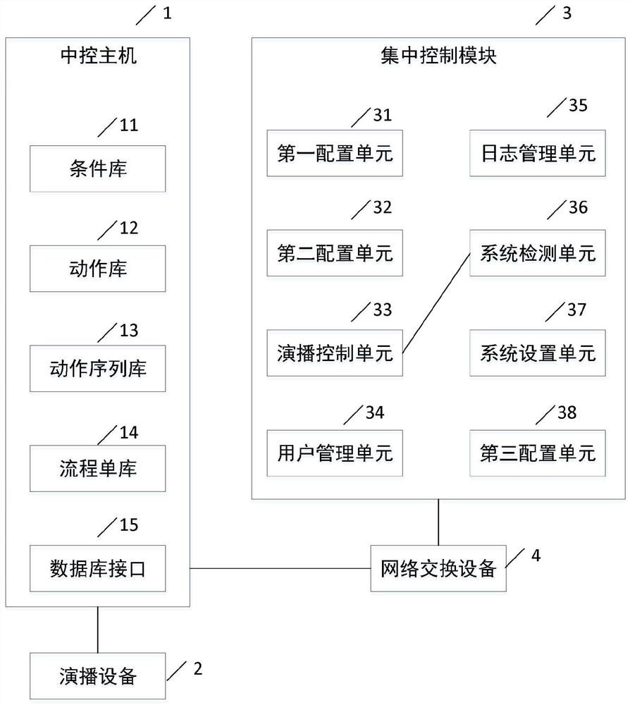
[0025] In a preferred embodiment of the present invention, based on the above-mentioned problems existing in the prior art, a centralized studio control system is now provided, such as figure 1 shown, including:

[0026] At least one central control host 1 is connected to multiple studio devices 2 respectively. The central control host 1 includes:

[0027] Condition library 11, used to save the preset trigger conditions of each studio equipment 2;

[0028] Action library 12, used to save preset trigger actions of each studio device 2;

[0029] The centralized control module 3 is connected to the central control host 1, and the centralized control m...


PUM


Abstract

The invention provides a studio centralized control system, and the system comprises at least one central control host which comprises a condition library used for storing trigger conditions of all studio devices; an action library which is used for storing the triggering action of each piece of studio equipment; a centralized control module which comprises a first configuration unit which is used for extracting a plurality of triggering actions according to program scene presetting, arranging the triggering actions to obtain an action sequence and storing the action sequence in an action sequence library; a second configuration unit which is used for presetting and extracting a plurality of triggering actions and associated triggering conditions according to a program flow, setting interval time between the triggering actions to obtain a flow list and storing the flow list in a flow list library; and an studio control unit which is used for making studio programs according to the condition library, the action library, the action sequence library and the flow list library, and receiving a studio control instruction input externally in the studio process to control each studio device in a linkage manner. The invention has the beneficial effects that the program production efficiency is improved, human errors caused by cooperative operation are reduced, and the labor cost and the communication cost are saved.

Description

technical field [0001] The invention relates to the technical field of program production, in particular to a studio centralized control system. Background technique [0002] With the development of the Internet, the content production and packaging of radio and television programs have become more and more diversified, and more and more studio equipment needs to be used in the broadcast process. The addition of various studio equipment in the program production and broadcast process makes various types of work The problem of cooperation between personnel has become increasingly prominent. Manual operations often cannot ensure the accuracy of time and space control of each studio equipment, and the existence of human factors will increase occasional situations and affect the normal operation of program production and broadcasting. Based on the above problems, centralized studio control, as an emerging technology, is valued by major TV stations. [0003] The existing central...

Claims


Application Information

Patent Timeline
Patent Type & Authority Applications(China)
IPC IPC(8): H04N5/222H04N5/262
CPCH04N5/222H04N5/262Y02P90/02
Inventor 江海波奚培张云华张忠辉徐侃陈洲
Owner 上海文化广播影视集团有限公司
Why Eureka
Eureka Blog
Learn More