Efficient grinding fluid stirrer

A technology of grinding liquid and agitator, which is applied in the direction of mixer accessories, springs/shock absorbers, chemical instruments and methods, etc. It can solve the problems of affecting the use effect of grinding liquid, low efficiency of grinding liquid mixing, and difficulty in stirring, etc.

Pending Publication Date: 2021-08-06
SHENZHEN COFUN GRINDING MATERIALS CO LTD
View PDF7 Cites 1 Cited by
  • Summary
  • Abstract
  • Description
  • Claims
  • Application Information

AI Technical Summary

Problems solved by technology

[0003] Generally, when producing grinding liquid, it is necessary to mix and stir the grinding liquid. During the stirring process, the stirring rod is used to stir in the same direction. It takes a long time to stir, and it is usually difficult to stir the raw materials at the bot...

Method used


Image

  • Efficient grinding fluid stirrer
  • Efficient grinding fluid stirrer
  • Efficient grinding fluid stirrer

Examples


Embodiment 1

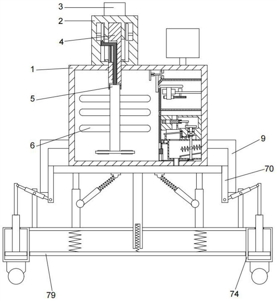
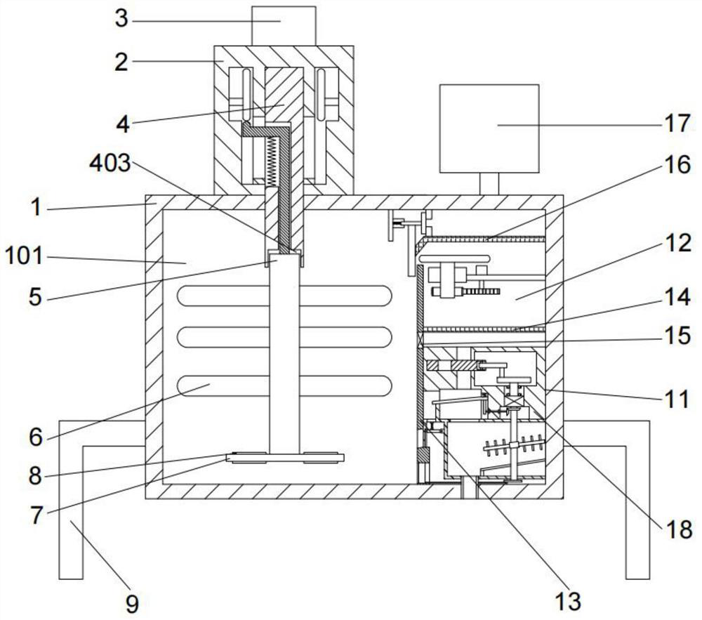
[0056] Embodiments of the present invention provide a high-efficiency grinding liquid agitator, such as Figure 1-3 As shown, it includes a shell 1 and a power shell 2, the upper end of the shell 1 is fixedly provided with the power shell 2, the side end of the shell 1 is evenly distributed with a number of brackets 9 in the circumferential direction, and the shell 1 is connected by a partition 13. Divided into a stirring chamber 101 and a processing chamber, the processing chamber is divided into a feeding chamber 12 and a filtering chamber 11 from top to bottom by a partition 2 14, and the stirring chamber 101 communicates with the feeding chamber 12 and the filtering chamber 11 respectively, The inside of the filter cavity 11 is provided with a filter assembly, the filter assembly includes a filter bin 1803 and a filter residue bin 1805, the power shell 2 is rotationally connected with the rotation shaft 1 4, and the power shell 2 is provided for driving the The rotating sh...

Embodiment 2

[0061] On the basis of above-mentioned embodiment 1, as Figure 1-5 As shown, the upper end of the power shell 2 is fixed with the motor one 3, and an adjustment device is also connected between the rotation shaft one 4 and the stirring rod 5, and the adjustment device includes: the rotation shaft one 4 The opening slot 401 provided on the left side of the upper part, the middle part of the rotating shaft one 4 is provided with the movable chamber two 402, the bottom of the rotating shaft one 4 is provided with the installation groove 403, the opening groove 401, the movable chamber two 402 and The installation groove 403 is sequentially connected up and down;

[0062] The upper end of the power housing 2 is fixed with a motor 3, and the upper side of the power housing 2 is provided with a mounting hole 201, and the mounting hole 201 is rotatably connected with the rotating shaft 4, and the rotating shaft 4 The upper end of the power shell 2 is fixedly connected with the moto...

Embodiment 3

[0067] On the basis of Example 1, such as Figure 6 As shown, the feeding chamber 12 communicates with the feeding bin 17 through the feeding port 1701 passing through the housing 1, and a feeding assembly is provided inside the feeding chamber 12, and the feeding assembly includes:

[0068] Support plate one 16, the support plate one 16 and the upper end of the housing 1 form a liquid storage chamber 1201, the upper and lower ends of the left side of the liquid storage chamber 1201 are symmetrically provided with stoppers 36, and between the stoppers 36 There is a through hole 3601, the left side of the through hole 3601 is provided with a baffle 35, the baffle 35 is fixedly connected with the connecting rod 31, and the lower end of the connecting rod 31 is fixedly provided with a baffle 2 30, the The first connecting rod 31 is fixedly connected with the second spring 33, the second spring 33 is fixedly arranged inside the sleeve 32, the first connecting rod 31 is slidably co...


PUM


Abstract

The invention provides an efficient grinding fluid stirrer which comprises a shell and a power shell; the power shell is fixedly arranged at the upper end of the shell, a plurality of supports are evenly distributed at the side end of the shell in the circumferential direction, and a stirring cavity, a filtering cavity and a feeding cavity are formed in the shell; the power shell is rotationally connected with a first rotating shaft; the first rotating shaft penetrates through the shell and enters the interior of the stirring cavity; and a stirring rod is arranged at the lower end of the first rotating shaft, a plurality of blades are symmetrically arranged on the left side and the right side of the stirring rod, and a stirring assembly is fixedly connected to the bottom end of the stirring rod. The technical problems that in the stirring process, stirring is carried out in the same direction through the stirring rod, the needed stirring time is long, raw materials at the bottom of a stirring chamber are usually difficult to stir, the grinding fluid mixing efficiency is low, then the raw materials at the bottom of the stirring chamber cannot be evenly mixed, the raw material mixing effect is poor, and the use effect of the grinding fluid is influenced are solved through the stirring assembly.

Description

technical field [0001] The invention relates to the technical field of grinding liquid production, in particular to a high-efficiency grinding liquid agitator. Background technique [0002] The grinding fluid is divided into oil-based grinding fluid and water-based grinding fluid. The grinding fluid can cool the workpiece during grinding, and cool the tool in time, which can significantly reduce the wear of the tool, and has excellent rust resistance for equipment and workpieces. [0003] Generally, when producing grinding liquid, it is necessary to mix and stir the grinding liquid. During the stirring process, the stirring rod is used to stir in the same direction. It takes a long time to stir, and it is usually difficult to stir the raw materials at the bottom of the mixing chamber, so that the grinding liquid The mixing efficiency is relatively low, so that the raw materials at the bottom of the mixing chamber cannot be uniformly mixed, and the mixing effect of the raw ma...

Claims


Application Information

Patent Timeline
IPC IPC(8): B01F11/00B01F15/00B01F15/02B01F15/04B01D33/01B01D33/76B01F3/20F16F15/067F16F15/02B01F23/70
CPCB01D33/0158B01D33/76F16F15/067F16F15/02B01F23/708B01F31/00B01F31/40B01F35/2115B01F35/42B01F35/187B01F35/714B01F35/71B01F35/88
Inventor 殷浩之张超
Owner SHENZHEN COFUN GRINDING MATERIALS CO LTD
Why Eureka
Try Eureka