Automatic detection device for cylindrical automobile parts
An automatic detection device and auto parts technology, applied in the field of parts detection, can solve problems such as inaccurate measurement, loud noise, mixed defective products and lower pass rate of factory parts, so as to improve detection efficiency, accurate detection structure and save labor cost effect
- Summary
- Abstract
- Description
- Claims
- Application Information
AI Technical Summary
Problems solved by technology
Method used
Image
Examples
Embodiment 1
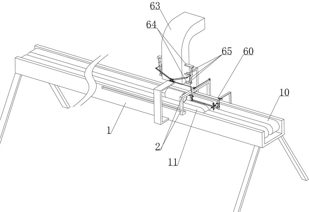
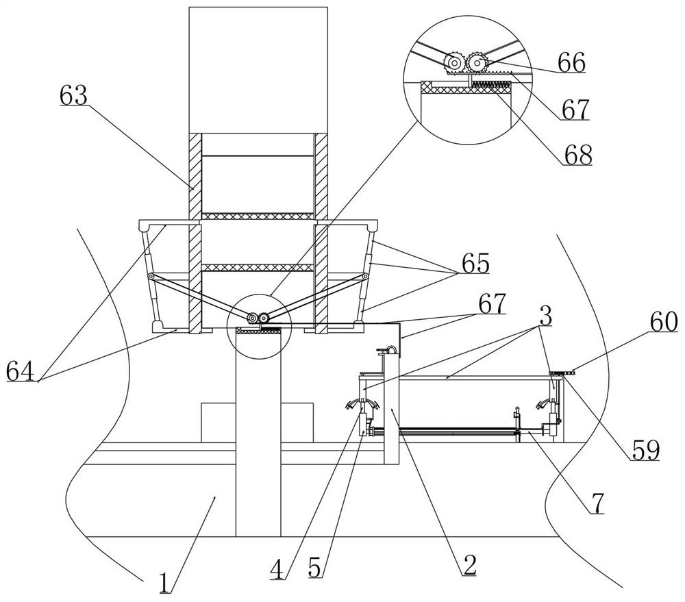
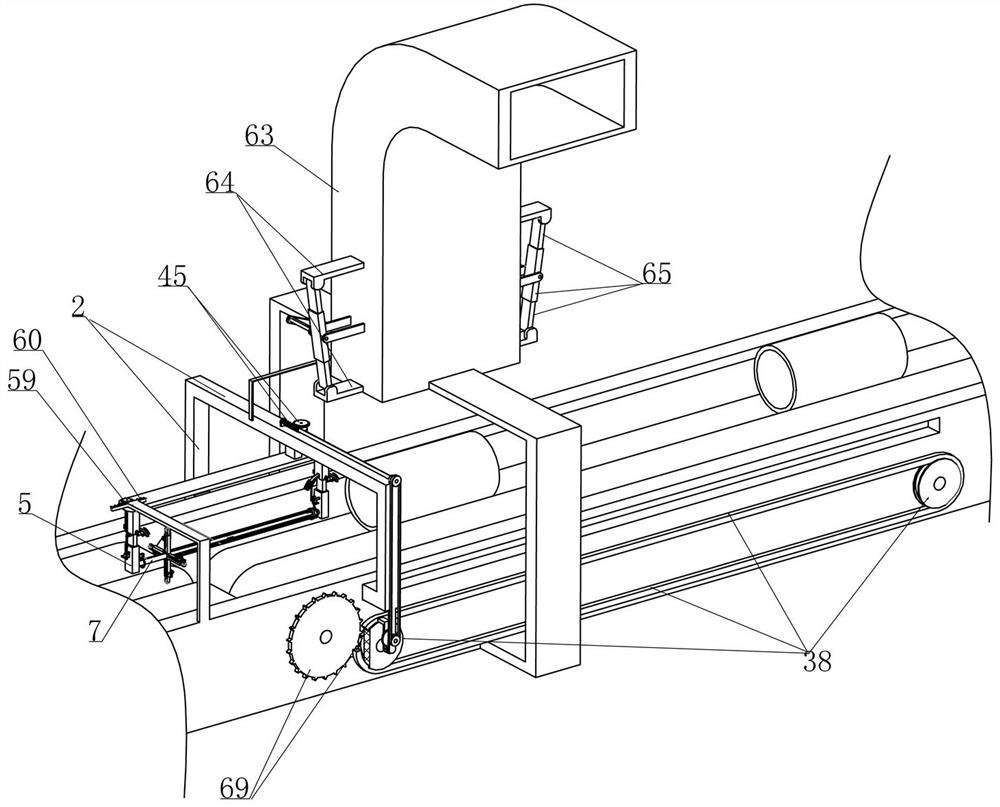
[0037] Embodiment 1, this embodiment provides an automatic detection device for cylindrical auto parts, as attached figure 1 As shown, the frame body 1 is included and the frame body 1 is provided with a transport unit 11 (the conveying direction of the transport unit is along the figure 1 shown in the left direction), the improvement of this scheme is that we slide the detection frame 2 horizontally on the frame body 1 and install the U-shaped frame 3 vertically on the detection frame 2 (that is, we can pass Adjust the vertical position of the U-shaped frame 3 and then realize the adjustment of the distance between the U-shaped frame 3 and the part to be tested. The detection frame 2 and the U-shaped frame 3 can be connected by an electric telescopic rod. The specific connection structure will not be done here. More description), as attached Figure 6 As shown, the two cantilevers of the U-shaped frame 3 are vertically slidably mounted with the lifting rod 4 and the U-shaped...
Embodiment 2
[0043] Embodiment 2, on the basis of embodiment 1, as attached Figure 7 As shown, the lateral sides of the elevating rod 4 close to the parts are integrally provided with arc rods 13 at the beginning, and the lateral sides of the elevating rod 4 away from the parts are initially provided with arc rods 13 (due to the fact that during the entire detection process, the initial The elevating rod 4 away from the parts will not pass through the parts inner cavity wall, so only an arc rod 13) is set, as attached Figure 7 , 8 As shown, when the reciprocating pulley group 38 drives the detection frame 2 to move, the unlocking plate 16 close to the part first touches the end face of the part and forces the unlocking plate 16 to slide along the radial direction of the corresponding arc rod 13 ( unlocking spring 17 is compressed), the linkage mechanism includes a first connecting rod 19 that is rotatably installed with the unlocking plate 16 and the first connecting rod 19 is slidably ...
Embodiment 3
[0046] Embodiment 3, on the basis of embodiment 2, as attached Figure 6 As shown, on the detection rod 7 near one of the rectangular tubes 5 (that is, the rectangular tube 5 vertically slidingly matched with the elevating rod 4 with only one arc-shaped rod 13) is surrounded by a number of slides along its radial interval. cavity 22 and the detection wheel 8 is slidably installed in the corresponding sliding cavity 22 (as attached Figure 5 As shown, the detection wheel 8 is rotated and installed with a mounting rod and the mounting rod is slidably installed in the sliding cavity 22, the mounting rod is not labeled in the figure), the stroke amplification device includes the first enlarged rack 23 connected with the mounting rod and the first enlarged tooth The bar 23 is meshed with a first amplifying gear 24 that is rotatably mounted on the sliding chamber 22. The first amplifying gear 24 rotates coaxially with a second amplifying gear 25 and the second amplifying gear 25 dri...
PUM
 Abstract
Description
Claims
Application Information
 - R&D
- Intellectual Property
- Life Sciences
- Materials
- Tech Scout
- Unparalleled Data Quality
- Higher Quality Content
- 60% Fewer Hallucinations
Browse by: Latest US Patents, China's latest patents, Technical Efficacy Thesaurus, Application Domain, Technology Topic, Popular Technical Reports.
© 2025 PatSnap. All rights reserved.Legal|Privacy policy|Modern Slavery Act Transparency Statement|Sitemap|About US| Contact US: help@patsnap.com


