
Power reserve prediction control method for tandem electromechanical composite transmission system

An electromechanical composite transmission and power reserve technology, applied in hybrid vehicles, motor vehicles, control devices, etc., can solve problems such as engine speed shock, bus voltage drop in the electromechanical composite transmission system, and failure to consider engine operating characteristics. The effect of speed shock or flameout

Active Publication Date: 2021-08-06
BEIJING INSTITUTE OF TECHNOLOGYGY
View PDF8 Cites 0 Cited by
  • Summary
  • Abstract
  • Description
  • Claims
  • Application Information

AI Technical Summary

Problems solved by technology

[0007]1. Existing control technologies ideally control the electromechanical compound transmission system without considering the working characteristics of the engine
[0008]2. To control the power flow of the electromechanical compound transmission system, it is necessary to adjust the speed of the engine generator set. However, due to the different external characteristics of the engine and generator, the speed regulation process Slow, when the power generation load suddenly increases, it will cause the engine speed to fluctuate, and even cause the engine to stall in severe cases
[0009]3. When the electric power demand of the serial electromechanical compound transmission system vehicle is too large such as rapid acceleration and uphill, the generator cannot meet the power supply demand due to the delay of the engine response , it is easy to cause instantaneous high-power discharge of the power battery or even automatic protection, so that the bus voltage of the electromechanical compound transmission system drops, and the drive motor cannot work normally

Method used


Image

  • Power reserve prediction control method for tandem electromechanical composite transmission system
  • Power reserve prediction control method for tandem electromechanical composite transmission system

Examples


Embodiment Construction

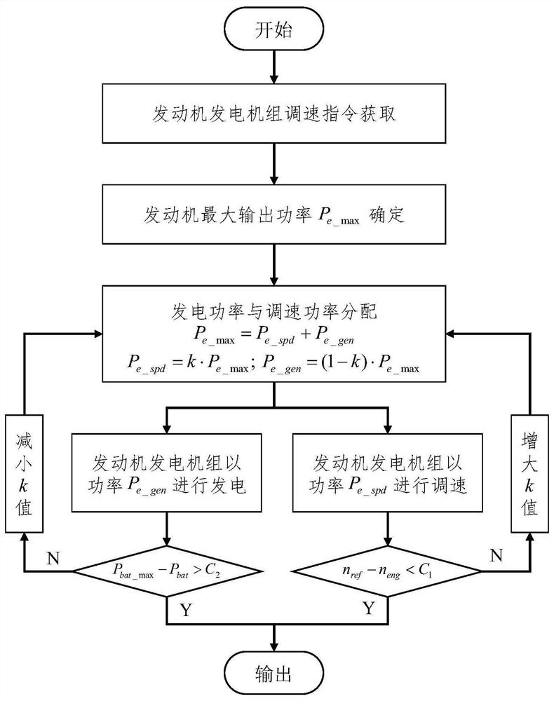
[0037] The specific technical solutions of the present invention are described in conjunction with the accompanying drawings.

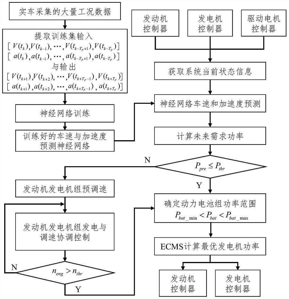
[0038] The flow chart of the power reserve predictive control method for the series electromechanical compound transmission system is as follows: figure 1 Shown:

[0039] A power reserve predictive control method for a serial electromechanical compound transmission system, comprising the following steps:

[0040] S1. Extract vehicle speed and acceleration sequences from a large amount of data collected by real vehicles as an output training set, perform neural network training, and train the neural network offline for real-time vehicle speed and acceleration prediction;

[0041] Apply the historical data of vehicle driving as a training set, train the neural network for predicting vehicle speed and acceleration, and use it as a tool to indirectly predict vehicle demand power;

[0042] S2. Obtain the current state information of the system through the ...


PUM


Abstract

The invention provides a power reserve prediction control method for a tandem electromechanical composite transmission system. The method comprises the following steps: employing the historical data of vehicle driving as a training set, and training a neural network for predicting the vehicle speed and acceleration; according to the vehicle state data sampled at the current moment and the previous moment, applying the trained neural network to predict the vehicle speed and the acceleration within 2-3 seconds in the future, and further calculating the required power of the vehicle in the future time domain; when it is predicted that the current rotating speed of the generator cannot meet the future required power, pre-speed-regulation control is conducted on the engine generator set at the current moment, the rotating speed of the engine generator set is increased in advance, and the power reserve of the engine generator set is increased so as to meet the power generation power requirement at the future moment. The problems of slow speed regulation of the engine and over-discharge of the power battery pack during high-power demand are solved, the power generation demand is met during speed regulation, and rotating speed oscillation or flameout of the engine during speed regulation of the engine is prevented.

Description

technical field [0001] The invention provides a power reserve predictive control method of a serial electromechanical compound transmission system, which belongs to the field of new energy vehicles. Background technique [0002] The series electromechanical compound transmission system consists of an engine, a generator, a power battery pack, a left / right drive motor, a coupling mechanism, a deceleration mechanism, and a corresponding controller. The system can be divided into a power generation unit and a drive unit structurally. The engine and generator are integrated with the engine generator set, which forms a power generation unit with the power battery pack. The engine generator set is a controllable power generation device, and the power battery pack is a device for passively compensating electric energy; the power consumption of the two drive motors passes through the coupling mechanism and the reduction mechanism. Output power externally to form a drive unit. The p...

Claims


Application Information

Patent Timeline
Patent Type & Authority Applications(China)
IPC IPC(8): B60W20/00B60W50/00
CPCB60W20/00B60W50/00B60W2050/0019Y02T10/62
Inventor 杨超陈瑞虎王伟达马越王暮遥杨刘权查明军项昌乐
Owner BEIJING INSTITUTE OF TECHNOLOGYGY
Learn More