Flexible comprehensive draw bar suitable for rotorcraft

A technology for a rotorcraft and a tow bar, applied in the field of tow bars, can solve the problems that the tow bar cannot be adjusted, has no interchangeability and versatility, cannot be temporarily replaced, etc., and achieves convenient towing connection work, convenient storage and The effect of transportation and practicability

Pending Publication Date: 2021-08-06
新乡市永安机械设备有限公司
View PDF0 Cites 0 Cited by
  • Summary
  • Abstract
  • Description
  • Claims
  • Application Information

AI Technical Summary

Problems solved by technology

[0002] The towing bar is suitable for the towing work of the rotorcraft. The force transmission between the tractor and the towing equipment is carried out by the towing bar. For example, the displacement of the rotorcraft on the ground is achieved by the traction of the tractor, and the tractor usually It is connected to the rotorcraft through the tow bar. At present, the structure of the tow bar is simple, and they are all in the form of a single rod. They are bulky and inconvenient to store. It can be adjusted, so it does not have interchangeability and versatility. It lacks a support structure, which brings certain difficulties to the work when it is used. Once a certain type of drawbar fails and cannot be used, it cannot be replaced temporarily, but it can be repaired. , leading to impact work, a flexible integrated traction bar suitable for rotorcraft is proposed for this problem

Method used


Image

  • Flexible comprehensive draw bar suitable for rotorcraft
  • Flexible comprehensive draw bar suitable for rotorcraft
  • Flexible comprehensive draw bar suitable for rotorcraft

Examples


Embodiment 1

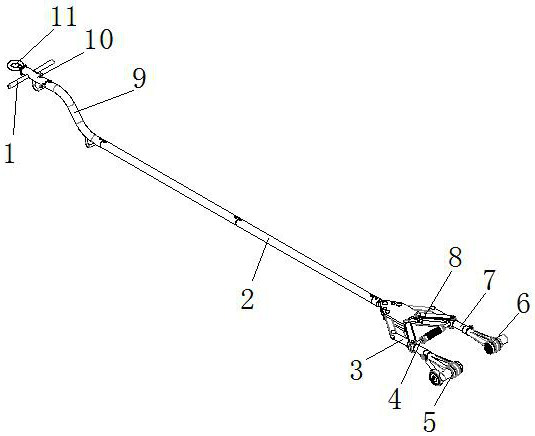
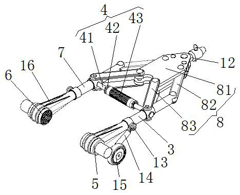
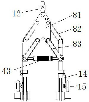
[0022] see Figure 1-5 , the present invention provides a technical solution: a flexible integrated traction rod suitable for rotorcraft, including a traction main rod 2, an adjustment locking mechanism 4, a left synchronous clamping beam 3, a right synchronous clamping beam 7, a left multi-pin Built-in flexible clamper 5, right multi-pin built-in flexible clamper 6, synchronous folding mechanism 8, traction buffer 10 and auxiliary wheel 15, adjustment locking mechanism 4 includes positioning double ear plate 81, left synchronous clamp The holding beam 3 is arranged on the left side of the positioning double ear plate 81, the right synchronous clamping beam 7 is placed on the right side of the positioning double ear plate 81, and the left synchronous clamping beam 3 and the positioning double ear plate 81 are synchronized with the right All be provided with the first movable plate 82 and the second movable plate 83 between the clamping beam 7 and the positioning double ear pla...


PUM

PropertyMeasurementUnit
Lengthaaaaaaaaaa

Abstract

The invention discloses a flexible comprehensive traction rod suitable for a rotor craft. The traction rod comprises a traction main rod, an adjusting locking mechanism, a left synchronous clamping beam, a right synchronous clamping beam, a left multi-pin embedded flexible clamper, a right multi-pin embedded flexible clamper, a synchronous folding mechanism, a traction buffer and auxiliary wheels, wherein the adjusting locking mechanism comprises a positioning double-lug plate, a left synchronous clamping beam is arranged on a left side face of the positioning double-lug plate, a right synchronous clamping beam is arranged on a right side face of the positioning double-lug plate, and a first movable plate and a second movable plate are arranged between the left synchronous clamping beam and the positioning double-lug plate and between the right synchronous clamping beam and the positioning double-lug plate correspondingly; the left multi-pin embedded flexible clamp holder is arranged at one end of the left synchronous clamping beam, and the right multi-pin embedded flexible clamp holder is arranged at one end of the right synchronous clamping beam. The traction rod is designed to be modular, can be quickly assembled, is convenient to store and transport, is convenient to adjust, and is high in universality.

Description

technical field [0001] The invention relates to the technical field of traction rods, in particular to a flexible integrated traction rod suitable for rotorcraft. Background technique [0002] The towing bar is suitable for the towing work of the rotorcraft. The force transmission between the tractor and the towing equipment is carried out by the towing bar. For example, the displacement of the rotorcraft on the ground is achieved by the traction of the tractor, and the tractor usually It is connected to the rotorcraft through the tow bar. At present, the structure of the tow bar is simple, and they are all in the form of a single rod. They are bulky and inconvenient to store. It can be adjusted, so it does not have interchangeability and versatility. It lacks a support structure, which brings certain difficulties to the work when it is used. Once a certain type of drawbar fails and cannot be used, it cannot be replaced temporarily, but it can be repaired. , leading to impa...

Claims


Application Information

Patent Timeline
IPC IPC(8): B64F1/22
CPCB64F1/224
Inventor 谢庆伟杨向东董海英王晓宇郭雷雷
Owner 新乡市永安机械设备有限公司
Why Eureka
Try Eureka