
Adsorption type range hood based on fluid pressure intensity

A range hood, adsorption technology, applied in the field of energy-saving range hood equipment, can solve the problems of increased power consumption, increased load, reduced speed, etc., to achieve the effect of avoiding load increase

Pending Publication Date: 2021-08-06
梁启明
View PDF0 Cites 1 Cited by
  • Summary
  • Abstract
  • Description
  • Claims
  • Application Information

AI Technical Summary

Problems solved by technology

[0006] The invention provides a range hood based on fluid pressure adsorption, which has the function of preventing direct contact between the oil fume and the high-speed rotating impeller, effectively avoiding excessive oil fume or impurities adhering to the impeller, effectively reducing the The load of the impeller when it rotates at high speed and the power consumption of the motor when it drives it to rotate at high speed improve the working efficiency, stability and reliability of the range hood, and solve the problem of the existing range hood due to the impeller When rotating at high speed, it will come into direct contact with the fume, and the fume generated in the kitchen has a relatively high viscosity, so that more fumes will adhere to the impeller of the range hood during long-term use, and the Viscous oil fume and more dust and other impurities adhere to it, resulting in the continuous increase of the load of the impeller when it rotates at high speed, which not only increases the power consumption of the motor when driving the impeller to rotate, but also reduces the speed of the impeller at rated power. Problems that lead to poor working efficiency and condition of the range hood

Method used


Image

  • Adsorption type range hood based on fluid pressure intensity
  • Adsorption type range hood based on fluid pressure intensity
  • Adsorption type range hood based on fluid pressure intensity

Examples


Embodiment Construction

[0029] The following will clearly and completely describe the technical solutions in the embodiments of the present invention with reference to the accompanying drawings in the embodiments of the present invention. Obviously, the described embodiments are only some, not all, embodiments of the present invention. Based on the embodiments of the present invention, all other embodiments obtained by persons of ordinary skill in the art without making creative efforts belong to the protection scope of the present invention.

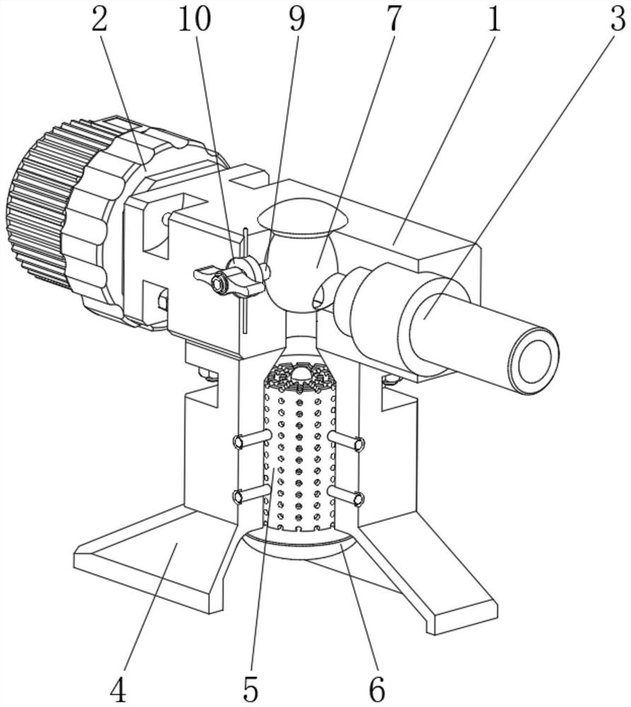
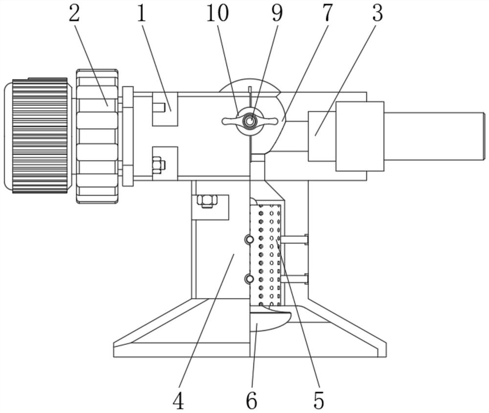
[0030] see Figure 1-2 , a range hood based on fluid pressure adsorption, including a fixed box body 1, one end of the fixed box body 1 is fixedly equipped with an impeller mechanism 2, and the other end of the fixed box body 1 is provided with a smoke exhaust pipe 3 connected to the outside thereof , and the middle part of the bottom end of the fixed box body 1 is provided with a smoking air duct 4 connected to its inner cavity, and the middle part of the inn...


PUM


Abstract

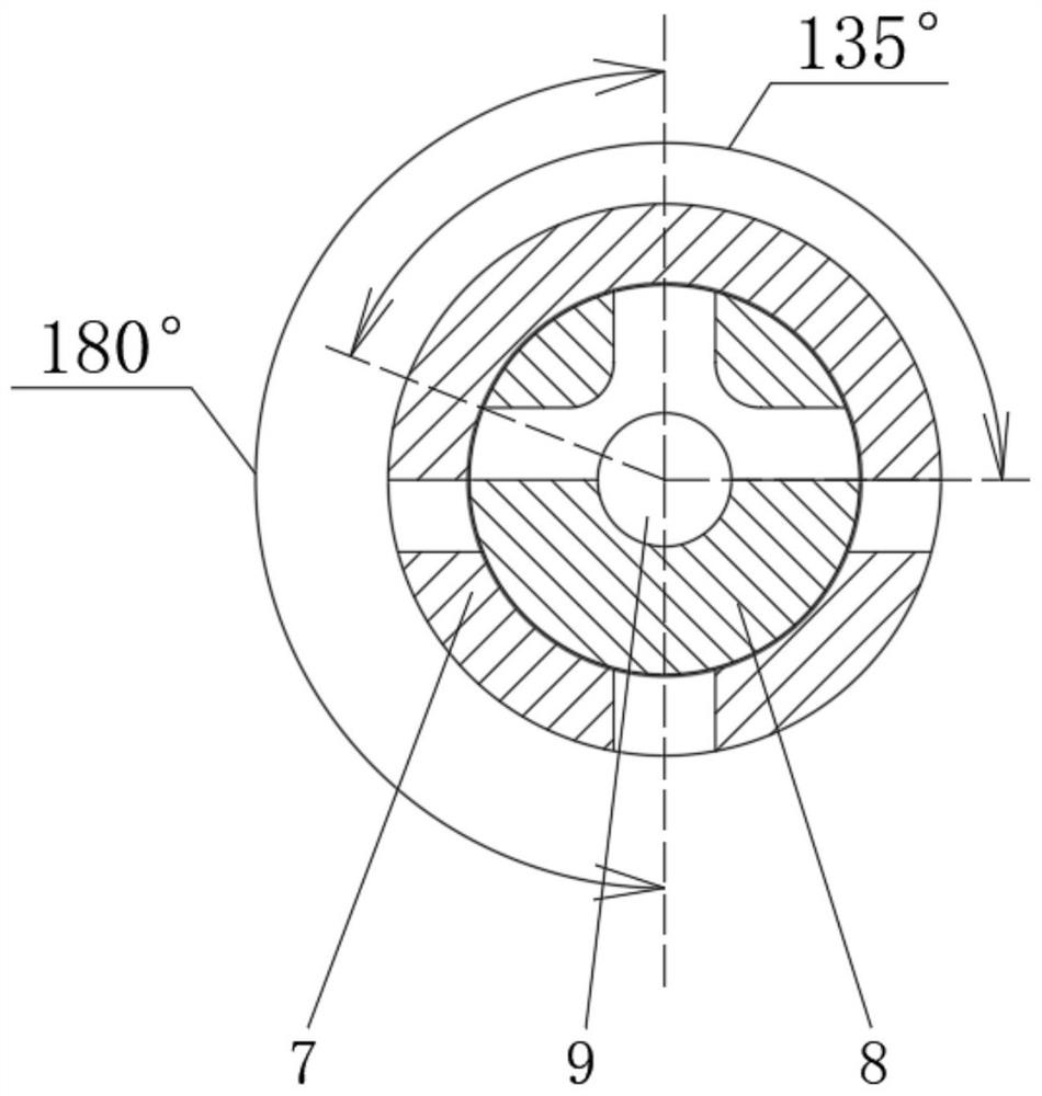
The invention relates to the technical field of energy-saving range hood equipment, and discloses an adsorption type range hood based on fluid pressure intensity. The adsorption type range hood comprises a fixed box body, one end of the fixed box body is fixedly provided with an impeller mechanism, and the other end of the fixed box body is provided with a smoke exhaust pipeline communicated to the outside of the fixed box body; and the middle part of the bottom end of the fixed box body is provided with a smoke suction air duct communicated to an inner cavity of the fixed box body, a filter screen is arranged in the middle of an inner cavity of the smoke suction air duct, and an oil collecting cup is clamped to the position, located at the bottom of the inner cavity of the smoke suction air duct, of the bottom end of the filter screen. According to the adsorption type range hood based on the fluid pressure intensity, the positions and angles between a conductive block I and a conductive block II on a control disc and a conductive ring on a movable disc are set, so that in the process of rotating the angle of a transmission connecting shaft, the range hood is turned on and turned off; and meanwhile, the exhaust power can be adjusted, so that the structural composition of the range hood is greatly simplified, and the range hood is simple to operate and convenient to use.

Description

technical field [0001] The invention relates to the technical field of energy-saving range hood equipment, in particular to a range hood based on fluid pressure adsorption. Background technique [0002] The range hood is a kitchen appliance used in the kitchen to remove the waste generated by the stove and the oil fume generated during the cooking process and send it to the outside, so as to reduce pollution and purify the air. It is mainly used The negative pressure generated by the high-speed rotating impeller in the air duct of the chassis can draw away the smoke in the kitchen. [0003] However, the existing range hood will directly contact with the flue gas because the impeller rotates at high speed, and the oil fume produced in the kitchen has a relatively large viscosity, so that the range hood will be damaged during long-term use. More oil fume will adhere to the impeller, and more impurities such as dust will adhere to the viscous oil fume, resulting in the continu...

Claims


Application Information

Patent Timeline
Patent Type & Authority Applications(China)
IPC IPC(8): F24C15/20
CPCF24C15/2021F24C15/2035F24C15/2078
Inventor 梁启明
Owner 梁启明
Learn More