Camera and laser radar synchronization method and system of intelligent driving control system

A technology of laser radar and control system, which is applied in the field of camera and laser radar synchronization, and can solve problems such as difficult alignment of camera exposure time

CN113219479APending Publication Date: 2021-08-06环宇智行科技(苏州)有限公司
0 Cites 2 Cited by

Patent Information

Authority / Receiving Office
CN · China
Current Assignee / Owner
Publication Date
2021-08-06

Smart Images

  • Figure 1
    Figure 1
  • Figure 2
    Figure 2
  • Figure 3
    Figure 3
Patent Text Reader

Abstract

The invention provides a camera and laser radar synchronization method and system of an intelligent driving control system, and the method comprises the steps: calculating the synchronization delay time of the exposure time of the camera according to the frame rate and the installation angle of the camera, and enabling the exposure time to be just the same as the time when the laser radar scans the angle; at the moment, laser radar data and camera data can be subjected to fusion processing, and accurate time and space information is obtained.
Need to check novelty before this filing date? Find Prior Art

Description

technical field

[0001] The invention relates to the technical field of intelligent driving control, in particular to a camera and laser radar synchronization method and system of an intelligent driving control system. Background technique

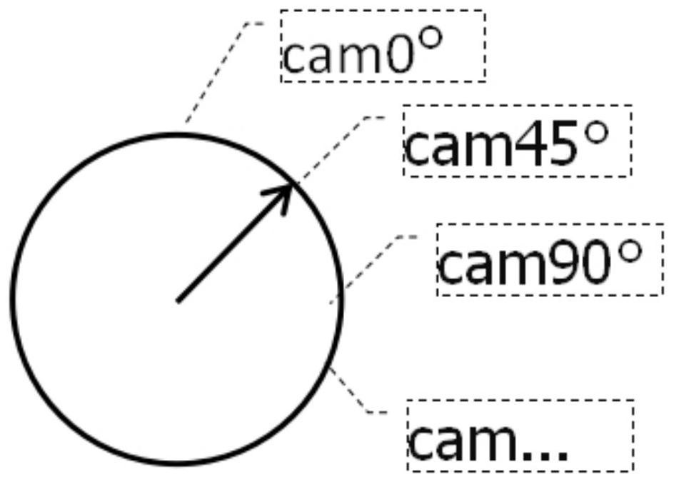
[0002] Intelligent driving control technology requires the precise synchronization of multiple channels of data such as video, radar, and inertial navigation to realize the associated calculation of time and space. At present, the mainstream sensors in the intelligent driving industry are cameras and lidars. Lidars are connected through Ethernet and scan 360° at 10 or 30rps (revolutions per second). Cameras are installed in the front, side front, side rear, rear view, etc. 0-360° angle, the camera is connected through MIPI, and the video data is shot at a frame rate of 10 or 30fps (frame / second). The time interval between two frames of data is relatively large. On a high-speed moving vehicle, data at different times corresponds to differe...

Examples

Embodiment Construction

[0042] The following will clearly and completely describe the technical solutions in the embodiments of the present invention in conjunction with the embodiments of the present invention. Obviously, the described embodiments are only part of the embodiments of the present invention, not all of them. Based on the implementation manners in the present invention, all other implementation manners obtained by persons of ordinary skill in the art without making creative efforts belong to the scope of protection of the present invention.

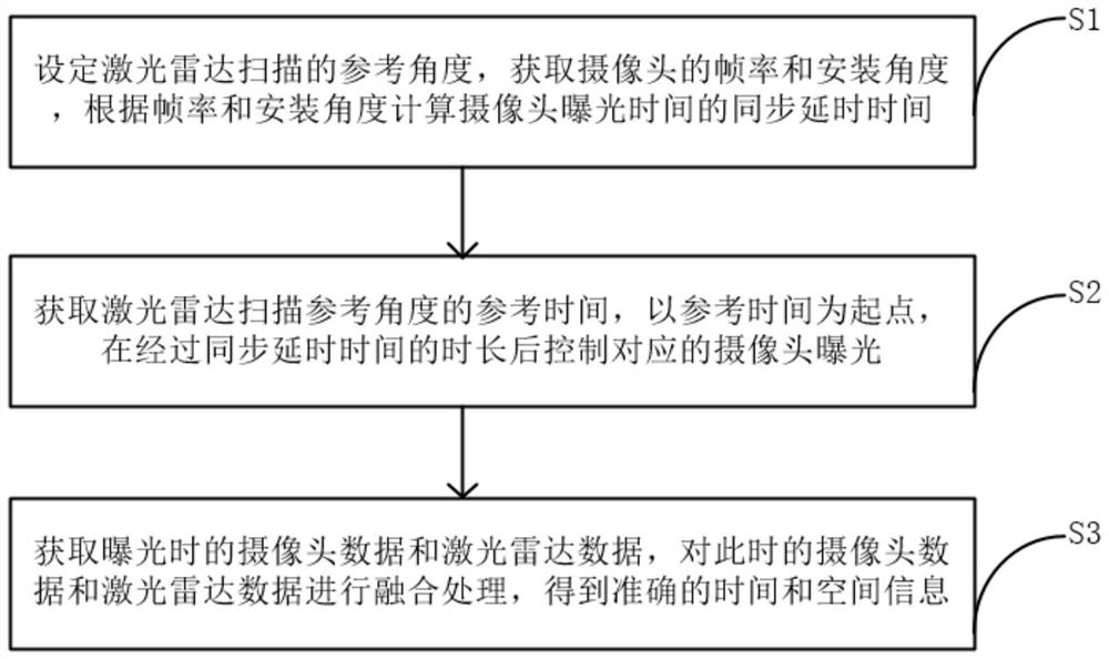
[0043] Such as figure 1 As shown, the camera and lidar synchronization method of the intelligent driving control system of this embodiment includes:

[0044] Step S1, setting the reference angle for lidar scanning, obtaining the frame rate and installation angle of the camera, and calculating the synchronization delay time of the exposure time of the camera according to the frame rate and installation angle;

[0045] Step S2, obtain the reference ...