
Communication system of upper computer and PLC

A technology of communication system and bit computer, which is applied in general control system, control/adjustment system, program control in sequence/logic controller, etc. It can solve the problems of data processing process crossover, poor reliability, data error, etc., and achieve a wide range of Effects of exploiting value, ensuring validity and accuracy, and improving reliability

Active Publication Date: 2021-08-06
天津宜科自动化股份有限公司
View PDF19 Cites 0 Cited by
  • Summary
  • Abstract
  • Description
  • Claims
  • Application Information

AI Technical Summary

Problems solved by technology

However, since there may be multiple data processing processes in the PLC at the same time, it is easy for different data processing processes to overlap, resulting in data interaction errors, or, in the process of data transmission, affected by network communication, equipment itself, etc. Error, but it is still directly cleared by default to execute the next data interaction operation, which makes it impossible to detect data errors in time
And if the clearing fails, the result of the previous interaction data may be directly used in the next data interaction scene, resulting in data errors. Therefore, the existing host computer and PLC communication technology cannot guarantee the validity of the data in the communication process and accuracy, poor reliability

Method used


Image

  • Communication system of upper computer and PLC
  • Communication system of upper computer and PLC
  • Communication system of upper computer and PLC

Examples


Embodiment 1

[0023] In the scenario where the PLC acquires the target data from the upper computer, the step S100 includes:

[0024] Step S1, the data interaction channel of the PLC receives the first data interaction request sent by the external device connected to the PLC, and judges whether the state value of M1M2 corresponding to the data interaction channel is 00, and if so, the data interaction M1 of the channel becomes 1, and sends the first target data acquisition request to the upper computer;

[0025] It can be understood that the external device can be an electrical device on a specific production line, such as an electrical device on a vehicle production line, and the specific first target data also depends on the electrical device. Vehicle assembly parameter information.

[0026] Step S2, the host computer monitors that the status value of M1M2 of the data interaction channel changes from 00 to 10, and obtains the first target data from the host computer database based on the...

Embodiment 2

[0036] The PLC is also used to obtain the connected device status data, store it in the preset data buffer area in the PLC, or store it in real time in the data points of the data interaction channel corresponding to the device status data, understandably Yes, for scenarios that require accurate acquisition of device status data in real time, the device status data needs to be directly stored in the data points of the data interaction channel. For application scenarios such as data backup only, where the real-time performance of device status data is not high, the device status data can be stored in the data cache area, and the host computer can obtain it after a period of time. In the scenario where the host computer obtains the target data from the PLC, the step S100 includes:

[0037] Step S10, the host computer sends a second data interaction request to the data interaction channel of the PLC, and judges whether the state value of M1M2 corresponding to the data interaction...


PUM


Abstract

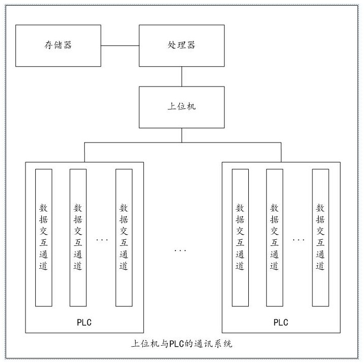
The invention relates to a communication system of an upper computer and a PLC. The communication system comprises an upper computer, a PLC, a processor and a memory in which a computer program is stored; data interaction channels are arranged in the PLC, each data interaction channel corresponds to a preset data interaction operation, a first signal interaction point M1, a second signal interaction point M2 and at least one data interaction point used for storing target data are arranged in each data interaction channel, the state value of M1 is 0 or 1, and the state value of M2 is 0 or 1; the PLC is allowed to perform read-write operation on the M1 of each data interaction channel and perform read-only operation on the M2 of each data interaction channel; the upper computer is allowed to perform read-write operation on the M2 and perform read-only operation on the M1; and the PLC and the upper computer monitor the state values of the M1M2 of the data interaction channels in real time and change the value M1 or the value M2, so that the data interaction operation of the PLC and the upper computer is completed. According to the invention, the validity and accuracy of data in the communication process of the upper computer and the PLC can be ensured, and the reliability of the communication between the upper computer and the PLC is improved.

Description

technical field [0001] The invention relates to the technical field of communication between an upper computer and a PLC, in particular to a communication system between an upper computer and a PLC. Background technique [0002] When the upper computer communicates with the PLC, that is, the upper computer and the programmable logic controller (Programmable Logic Controller, PLC for short) are two independent devices, and asynchronous communication is used between the two for data interaction. In the existing host computer and PLC communication technology, usually after a data interaction process is completed, the current interaction data in the PLC is cleared to zero by default, and then the next data interaction process is executed. However, since there may be multiple data processing processes in the PLC at the same time, it is easy for different data processing processes to overlap, resulting in data interaction errors, or, in the process of data transmission, affected b...

Claims


Application Information

Patent Timeline
Patent Type & Authority Applications(China)
IPC IPC(8): G05B19/05
CPCG05B19/054G05B2219/1194
Inventor 柴运营
Owner 天津宜科自动化股份有限公司
Learn More