Swing mechanism demonstration instrument and demonstration method thereof
A demonstrator and mechanism technology, applied in the field of swing mechanism demonstrator and its demonstration, to achieve the effect of self-excited vibration elimination
- Summary
- Abstract
- Description
- Claims
- Application Information
AI Technical Summary
Problems solved by technology
Method used
Image
Examples
Embodiment 1
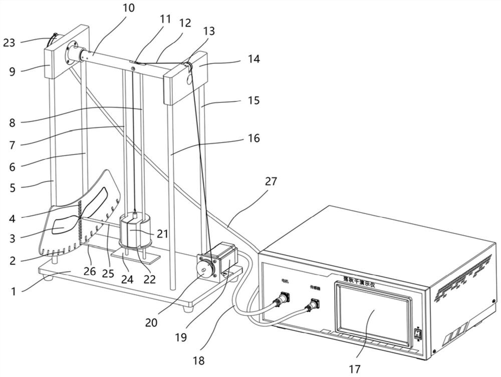
[0034] The present invention provides a swing mechanism demonstrator, which includes a rectangular base 1 that can be stably placed on the ground and four first uprights 5 of the same length, a second upright 6 and a third upright vertically fixed on the base 1 . rod 15 and a fourth vertical rod 16.
[0035] The top of the first vertical rod 5 and the second vertical rod 6 is fixedly connected with the first crossbeam 9, and the top of the third vertical rod 15 and the fourth vertical rod 16 is fixedly connected with the second crossbeam 14; The vertical rod 6 and the first cross beam 9 are symmetrically arranged with the third vertical rod 15, the fourth vertical rod 16 and the second cross beam 14. An angle sensor 23 connected to the rotating shaft 10 is installed on the outside of the first cross beam 9, and the angle sensor 23 passes through the angle sensor. A cable 27 connects the controller 17 .
[0036] A rotating shaft 10 is arranged between the first beam 9 and the ...
Embodiment 2
[0055] The present invention provides a swing mechanism demonstrator. The difference from Embodiment 1 is that the lifting rope 12 lifts the weight 21 to move up and down manually, and the motor cable connecting the controller 17 and the stepping motor 19 is removed. 18 to disconnect the power supply of the stepper motor 19, pull down the traction rope 12 from the driving wheel 20 of the stepper motor 19, hold the traction rope 12, adjust the length of the traction rope 12, and make the connecting rod 25 on the vertical ruler 4 A certain definite position, thereby determine the pendulum length when swinging, then hold the traction rope 12 and keep it in a tensioned state and still.
[0056] Turn on the power of the angle sensor 23 and the controller 17 to make the angle sensor 23 and the controller 17 in a standby state.
[0057] Confirm that the real-time data of state variables such as the swing angle and angular velocity have been displayed on the touch screen of the contro...
Embodiment 3
[0064] The present invention provides a swing mechanism demonstrator, which is different from Embodiment 2 in that the traction rope 12 is manually dragged to move the weight 21 up and down according to the law of "squatting high and standing low" so as to realize that the swing swings higher and higher. , change the frequency of "squat high and stand low", for example, complete the action of "squat high and stand low" twice in one swing cycle of the swing, or complete the action of "squat high and stand low" once in a swing cycle of the swing Actions can also be done in the two swing cycles of the swing, such as "high squat and low stand", etc., which can also make the swing higher and higher. At this time, the experimental device can demonstrate the difference between self-excited vibration and resonance .
PUM
 Abstract
Description
Claims
Application Information
 - R&D
- Intellectual Property
- Life Sciences
- Materials
- Tech Scout
- Unparalleled Data Quality
- Higher Quality Content
- 60% Fewer Hallucinations
Browse by: Latest US Patents, China's latest patents, Technical Efficacy Thesaurus, Application Domain, Technology Topic, Popular Technical Reports.
© 2025 PatSnap. All rights reserved.Legal|Privacy policy|Modern Slavery Act Transparency Statement|Sitemap|About US| Contact US: help@patsnap.com

