Shoe washing machine

A shoe washing machine and shoe washing technology, applied in the field of shoe washing machines, can solve the problems of damp, affecting the service life, stability and reliability cannot be guaranteed, etc.

Inactive Publication Date: 2021-08-10
四川鞋唰唰科技有限公司
View PDF0 Cites 0 Cited by
  • Summary
  • Abstract
  • Description
  • Claims
  • Application Information

AI Technical Summary

Problems solved by technology

[0004] The purpose of the present invention is to provide a shoe washing machine, which solves the problem that in the prior art, the electrical components in the equipment are located under the shoe washing space for a long time, and the electrical components are in a humid environment for a long time, which will cause dampness and affect the service life. , the problem that the stability and reliability of the use cannot be guaranteed

Method used


Image

  • Shoe washing machine
  • Shoe washing machine
  • Shoe washing machine

Examples


Embodiment 1

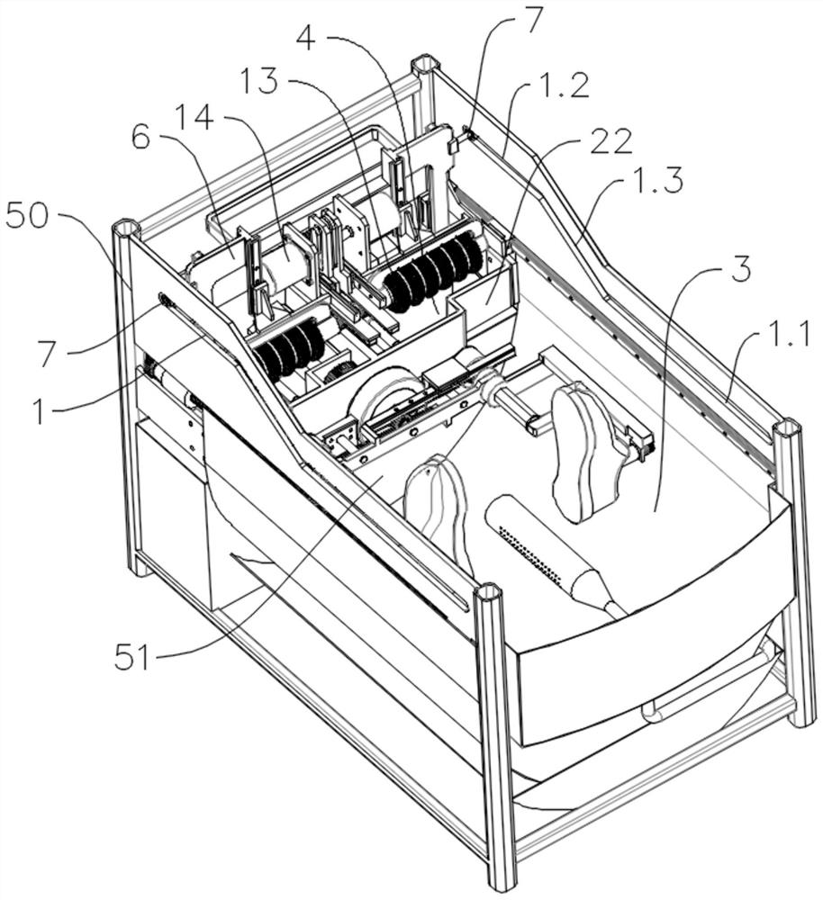
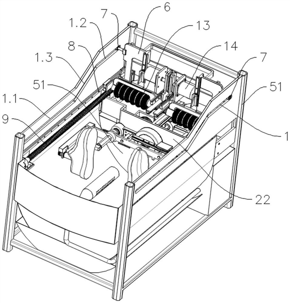
[0044] like Figure 1-Figure 8 As shown, the present embodiment provides a shoe washing machine, including a horizontal shoe washing box, a walking track 1, a shoe brush assembly, a walking drive mechanism for driving the shoe brush assembly to move along the walking track 1, and a horizontal shoe washing box There is an equipment rack 50 inside, and the walking track 1 is set on the equipment rack 50;

[0045] The walking track 1 is followed by the first track 1.1 and the second track 1.2 along its extending direction. The area corresponding to the first track 1.1 in the horizontal shoe washing box is the shoe washing area 3, and the horizontal shoe washing box is connected to the second track 1. 1.2 The corresponding area is the installation area 4, and a partition 51 is provided between the shoe washing area 3 and the installation area 4; when the shoe brush assembly moves to the first track 1.1, the shoe brush assembly is located in the shoe washing area 3, and the shoe br...

Embodiment 2

[0051] This embodiment is optimized on the basis of the above-mentioned embodiment 1.

[0052] Considering that in order to facilitate the installation of other mechanisms for driving the rotation angle of shoes in the installation area 4, to make room for the design of this part of the mechanism, the walking track 1 is followed by the first track 1.1, the transition track 1.3 and the second track along its extending direction. Two tracks 1.2, there is a height difference between the first track 1.1 and the second track 1.2, preferably, the first track 1.1 is selected to be lower than the second track 1.2, and the shoe brush assembly includes a mobile bracket 5 and a vertical sliding fit with the mobile bracket 5 The rolling brush work mobile support 6, the rolling brush work mobile support 6 is equipped with a rolling brush assembly, and the rolling brush work mobile support 6 is slidably matched with the walking track 1.

[0053]This kind of design, in the process of driving...

Embodiment 3

[0055] This embodiment is optimized on the basis of the above-mentioned embodiment 2.

[0056] The vertical sliding fit between the rolling brush assembly and the rolling brush working mobile support 6.

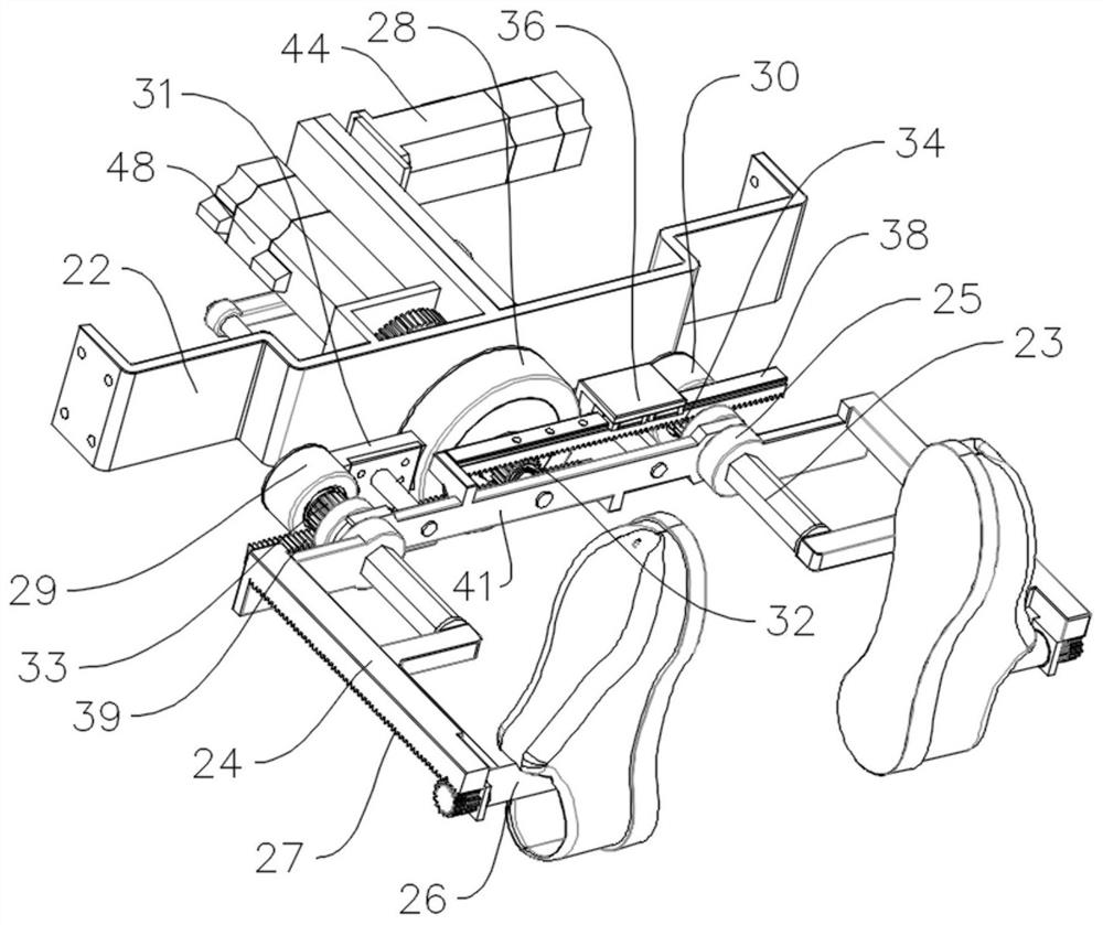
[0057] Currently, the moving device drives the roller brush to walk in a straight line, but the shoe has a curved shape. Therefore, the roller brush cannot effectively match the shape of the shoe during the straight-line walking process, and the scrubbing effect is not good. The vertical sliding fit between the rolling brush assembly and the rolling brush work moving support 6, then in the process that the rolling brush assembly moves along with the rolling brush work moving support 6, the rolling brush assembly can also move up and down along with the shape of the shoes, which can be more A good realization matches the shape of the shoe and the scrubbing effect is better.


PUM


Abstract

The invention relates to the technical field of shoe washing machines and discloses a shoe washing machine. The shoe washing machine comprises a horizontal shoe washing box, a walking track, a shoe brush assembly and a walking driving mechanism used for driving the shoe brush assembly to move along the walking track, wherein a first rail and a second rail are sequentially arranged on the walking rail in the extending direction of the walking rail, the area, corresponding to the first rail, in the horizontal shoe washing box is a shoe washing area, the area, corresponding to the second rail, in the horizontal shoe washing box is an installation area, and a partition plate is arranged between the shoe washing area and the installation area; when the shoe brush assembly moves to the first track, the shoe brush assembly is located in the shoe washing area, and when the shoe brush assembly moves to the second track, the shoe brush assembly is located in the mounting area. According to the shoe washing machine, problems that in the prior art, electric appliance elements in equipment are located below a shoe washing space for a long time, the electric appliance elements are located in a humid environment for a long time, the situation that the electric appliance elements are affected with damp occurs, the service life is affected, and use stability and reliability cannot be guaranteed are solved.

Description

technical field [0001] The invention relates to the technical field of shoe washing machines, in particular to a shoe washing machine. Background technique [0002] The structure of the traditional shoe washing machine is relatively simple. By setting the brush in the barrel, some of the brushes can be rotated to realize the scrubbing of the shoes. However, in the traditional shoe washing machine, multiple pairs of shoes are cleaned together, and there is no corresponding Fixed, during the cleaning process of the shoes, due to the impact of the water flow, the collision between the shoes and the collision between the shoes and the barrel wall will not only test the wear resistance of the shoes but also generate a lot of noise when the fuselage is running. It is difficult to clean the inside of the shoes by means of this method, so generally speaking, the cleaning effect is not good. Generally speaking, shoes that are not easily deformed can be cleaned by this drum cleaning ...

Claims


Application Information

Patent Timeline
Patent Type & Authority Applications(China)
IPC IPC(8): A47L23/02
CPCA47L23/02
Inventor 张魁范棣云文志林张石元王世顺张钰
Owner 四川鞋唰唰科技有限公司
Why Eureka
Try Eureka