A clamping mechanism for applying conductive paste to wire clips

A technology of clamping mechanism and conductive paste, which is applied to the device and coating of the surface coating liquid, which can solve the problems of economic loss, wire clip defect, wire clip shaking, etc., to improve the quality of coating, improve the efficiency of coating, Avoid the effect of axial wobble

Active Publication Date: 2022-07-26
JINHUA POWER TRANSMISSION & DISTRIBUTION ENG +1
View PDF8 Cites 0 Cited by
  • Summary
  • Abstract
  • Description
  • Claims
  • Application Information

AI Technical Summary

Problems solved by technology

[0002] Among the various electric fittings in the substation, the wire clip is used to connect the fixed lead wires, and there are wire clips in all the lead wires. It is widely used in the substation. Loose bolts at the wire clips will lead to poor connection of the drainage parts. If the load of the line increases, the temperature of the bad connection will rise rapidly, and a vicious circle will be generated, which will lead to more serious defects of the wire clips, and eventually thermal damage will occur. Due to the huge stock of wire clips in the substation, the wire clips The equipment failure caused by it has gradually become a common problem affecting the normal operation of my country's substations, and in the case of large-load single-circuit power supply, it is particularly prone to power grid accidents such as burning or disconnection, causing major economic losses
[0003] At present, the wire clip needs to be coated with a layer of conductive paste on the surface of the wire clip after installation. The existing conductive paste is manually operated by the operator, and the existing clamping mechanism is easy to cause the shaking of the wire clip during application, which will cause the conductive paste There are intermittent, thick and waste problems in the layer, and the clamping mechanism cannot adapt to the clamping of various types, and cannot quickly realize the clamping of the wire clamp

Method used


Image

  • A clamping mechanism for applying conductive paste to wire clips
  • A clamping mechanism for applying conductive paste to wire clips
  • A clamping mechanism for applying conductive paste to wire clips

Examples


Embodiment Construction

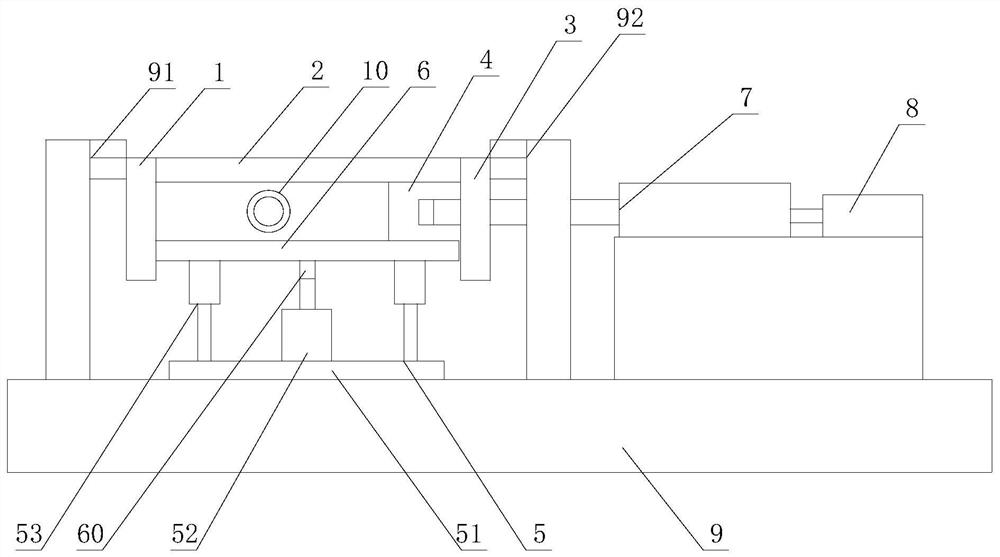
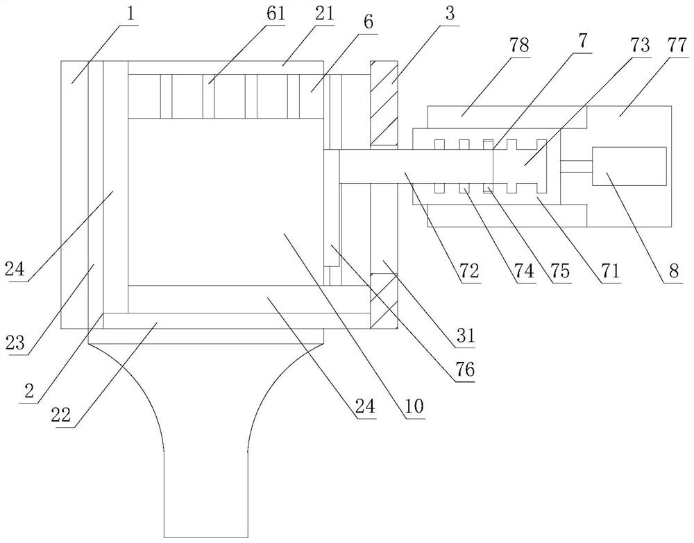
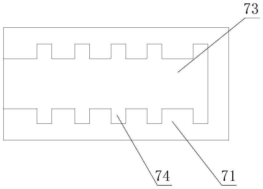
[0024] like figure 1 , figure 2 , image 3 , Figure 4 , Figure 5 As shown, a clamping mechanism for applying conductive paste to a wire clip includes a left baffle 1, an upper baffle 2 and a right baffle 3, and the upper baffle 2 is fixedly connected to the left baffle 1 and the right baffle 3, the left baffle 1, the upper baffle 2 and the right baffle 3 form a cavity 4 with a downward opening, and a height adjustment mechanism 5 is arranged in the cavity 4 along the height direction. The mechanism 5 includes a thrust cylinder 52 and a lower baffle plate 6 arranged on the thrust cylinder for placing the wire clip. The wire clip is fixed between the lower baffle plate 6 and the upper baffle plate 2 by means of the force of the thrust cylinder 52. The plate 1 or / and the right baffle 3 are provided with a width adjustment mechanism 7 for adjusting the width of the cavity 4. The width adjustment mechanism 7 is connected with a clamping cylinder 8 for controlling the width a...


PUM


Abstract

The invention relates to a clamping mechanism for applying conductive paste to a wire clip, comprising a left baffle, an upper baffle and a right baffle, and a height adjustment mechanism including a thrust cylinder and a lower baffle, a left baffle or / and a right baffle There is a width adjustment mechanism on the upper side, a clamping cylinder is connected to the width adjustment mechanism, and a smearing port is arranged on the upper baffle; The vertical direction of the wire clip is always subject to the force of the thrust cylinder, so the wire clip is not interfered by the smearing pressure when smearing, so that the surface of the wire clip is always in a horizontal state, thus effectively ensuring the uniform thickness of the conductive paste. Secondly, the width of the cavity is adjusted by the width adjustment mechanism, so it is only necessary to adjust the width of the width adjustment mechanism during installation to meet the needs of different types of wire clips, which improves the installation process of the wire clips.

Description

technical field [0001] The invention relates to a clamping mechanism for applying conductive paste to a wire clip. Background technique [0002] Among various power fittings in substations, wire clips are used to connect and fix lead wires, and all lead wires will have wire clips. They are widely used in substations. The loose bolts at the wire clips will lead to poor connection of the drainage components. If the line load increases from time to time, the temperature of the bad connection will rise rapidly, and a vicious circle will occur, resulting in more serious defects in the wire clip, and eventually thermal damage. The equipment failure has gradually become a common problem affecting the normal operation of my country's substations, and in the case of heavy-load single-circuit power supply, power grid accidents such as burnout or disconnection are particularly prone to occur, resulting in significant economic losses. [0003] At present, the wire clip needs to be coated...

Claims


Application Information

Patent Timeline
Patent Type & Authority Patents(China)
IPC IPC(8): B05C13/02B05C11/10
CPCB05C13/02B05C11/1002
Inventor 冯勇兵毛水强程辉阳马新华陈益坪林俊岑陈东郑恒刘新祝刚黄伟进胡雄伟李恒轩
Owner JINHUA POWER TRANSMISSION & DISTRIBUTION ENG
Why Eureka
Try Eureka