Turnover type side protective fence for battery replacing vehicle type and using method thereof
A technology for side fences and trams, which is applied to vehicle components, vehicle safety arrangements, transportation and packaging, etc., can solve the problems of low power exchange efficiency, cumbersome installation and disassembly, etc., and achieves high power exchange efficiency, easy installation and disassembly, and improved The effect of stability and reliability
- Summary
- Abstract
- Description
- Claims
- Application Information
AI Technical Summary
Problems solved by technology
Method used
Image
Examples
Embodiment 1
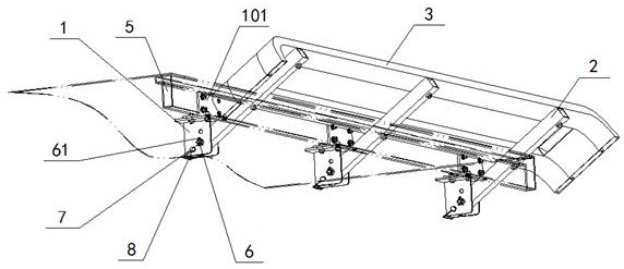
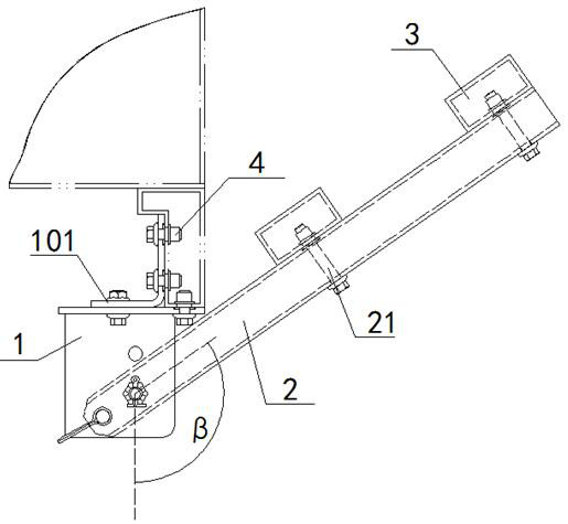
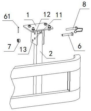
[0047] see Figure 1 to Figure 6 , a turnable side guardrail for battery-changing vehicles, including a plurality of fixed supports 1, the fixed supports 1 are in a U-shaped structure, and the bottom of the fixed supports 1 passes through the hole shaft 6 and the vertical beam of the guardrail 2 for rotational connection, one end of the opening shaft 6 is provided with a slotted nut 7, and the upper side of the guardrail vertical beam 2 is provided with a guardrail beam 3; The bottom beams 5 are connected, and a lock pin 8 is arranged on the fixed support 1 to fix the guardrail vertical beam 2 .
[0048] According to the above scheme, a method for using a flip-up side guardrail for changing electric vehicles, the method for using includes the following steps:
[0049] First, the guardrail vertical beam 2 is rotated around the opening shaft 6 until the guardrail vertical beam 2 is rotated to a vertical state, and then the lock pin 8 is inserted into the fixed support 1 to fix ...
Embodiment 2
[0051] Basic content is the same as embodiment 1, the difference is:
[0052] see Figure 1 to Figure 6 , the fixed support 1 is provided with a rotation hole 11, a vertical lock pin hole 12 and a flip lock pin hole 13, the vertical lock pin hole 12 is located above the rotation hole 11, and the vertical lock pin hole 12 and The rotating hole 11 is on the same vertical line, the diameter of the rotating hole 11 is the same as that of the vertical lock pin hole 12, the hole axis 6 is located in the flip lock pin hole 13, and the hole axis 6 and the flip lock pin hole 13, the lock pin 8 is located in the rotation hole 11 or the vertical lock pin hole 12, and the lock pin 8 is compatible with the rotation hole 11 and the vertical lock pin hole 12; the flip lock pin hole 13 is compatible with the rotation The angle β formed between the connection line of the hole 11 and the vertical line is 100-150 degrees; the lock pin 8 includes a lock pin shaft 14 and a lock pin retaining ring...
Embodiment 3
[0054] Basic content is the same as embodiment 1, the difference is:
[0055] see Figure 1 to Figure 6 , the opening shaft 6 is provided with an anti-loosening hole, and the cotter pin 61 is inserted into the anti-loosening hole after passing through the slotted nut 7; the fixed support 1 is provided with a fixed reinforcing plate 101, and the fixed reinforcing plate 101 In a right-angle shape, one side of the fixed reinforcement plate 101 is connected to the inner side of the side sill 5 of the cargo compartment, and the other side of the fixed reinforcement plate 101 is connected to the top position of the fixed support 1. The fixed reinforcement plate 101 The bottom of the bottom and the bottom of the side bottom beam 5 of the cargo compartment are on the same horizontal line; the guardrail beam 3 is provided with fastening bolts 21, and the guardrail beam 3 and the guardrail vertical beam 2 are connected by fastening bolts 21; Both the guardrail vertical beams 2 and the ...
PUM
 Abstract
Description
Claims
Application Information
 - R&D
- Intellectual Property
- Life Sciences
- Materials
- Tech Scout
- Unparalleled Data Quality
- Higher Quality Content
- 60% Fewer Hallucinations
Browse by: Latest US Patents, China's latest patents, Technical Efficacy Thesaurus, Application Domain, Technology Topic, Popular Technical Reports.
© 2025 PatSnap. All rights reserved.Legal|Privacy policy|Modern Slavery Act Transparency Statement|Sitemap|About US| Contact US: help@patsnap.com


