Municipal engineering sewer desilting device
A technology for dredging devices and sewers, applied in water supply devices, cleaning sewer pipes, waterway systems, etc., can solve problems such as poor sewage and blockage removal effects, and achieve good results, good cleaning effects, and high efficiency
- Summary
- Abstract
- Description
- Claims
- Application Information
AI Technical Summary
Problems solved by technology
Method used
Image
Examples
Embodiment 1
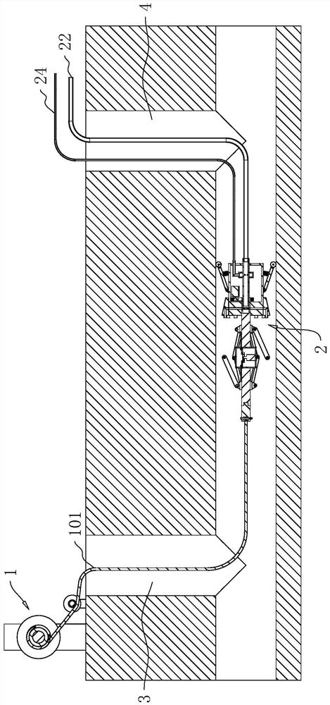
[0042] The embodiment of the application discloses a municipal engineering sewer dredging device. refer to figure 1The municipal engineering sewer dredging device includes a traction assembly 1 and a dredging assembly 2. The traction assembly 1 is arranged on one side of the left manhole cover 3 in the figure. The traction assembly 1 is wound with a steel wire rope 101, which can be threaded into the sewer And can be worn out from 4 places of right inspection shaft cover in the figure.
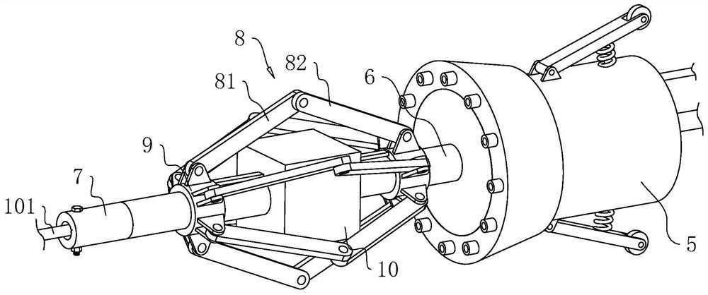
[0043] refer to figure 2 , the dredging assembly 2 includes a connection base 5, a rotation rod 6 is connected to the connection base 5, the end of the rotation rod 6 is connected to a connection head 7 in rotation, and the wire rope 101 can be fixed on the connection head 7, the traction wire rope 101, the wire rope 101 The connecting matrix 5 can be driven to pass through the sewer to clear the blockage.
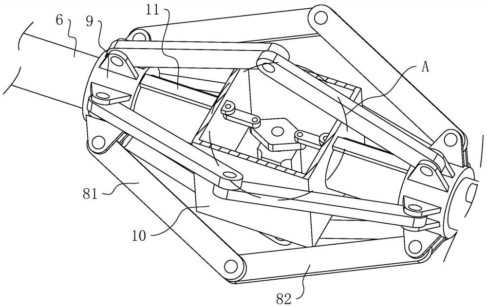
[0044] refer to figure 2 , the rotating rod 6 is provided with a stirring head, ...
Embodiment 2
[0056] The embodiment of the application discloses a municipal engineering sewer dredging device. refer to Figure 7 , the difference from Embodiment 1 is that the ends of the first stirring rod 81 and the second stirring rod 82 away from the hinge point are both slidingly connected with the rotating rod 6, specifically, the rotating rod 6 is provided with a plurality of sliding grooves 28. The sliding block 29 is fitted with a sliding clip in the sliding groove 28, the first stirring rod 81 and the second stirring rod 82 are hinged to the corresponding sliding block 29, and a return spring 30 is connected between the sliding block 29 and the protective cover 10 , One end of the return spring 30 is affixed to the sliding block 29, and the other end is affixed to the protective cover 10.
[0057] refer to Figure 7 A second driving motor 31 is fixedly connected to the protective cover 10, and a cam 32 is fixedly connected to the second driving motor 31 coaxially. The ends of...
PUM
 Abstract
Description
Claims
Application Information
 - R&D
- Intellectual Property
- Life Sciences
- Materials
- Tech Scout
- Unparalleled Data Quality
- Higher Quality Content
- 60% Fewer Hallucinations
Browse by: Latest US Patents, China's latest patents, Technical Efficacy Thesaurus, Application Domain, Technology Topic, Popular Technical Reports.
© 2025 PatSnap. All rights reserved.Legal|Privacy policy|Modern Slavery Act Transparency Statement|Sitemap|About US| Contact US: help@patsnap.com


