High-low voltage power distribution cabinet with anti-accidental-touch protection structure

A protection structure, high and low voltage technology, applied in substation/distribution device casing, electrical components, substation/switch layout details, etc., can solve problems such as easy collision with protective cover, large misoperation, easy to touch, etc., and achieve improvement The effect of stability, avoiding accidental touch, and improving tightness

Inactive Publication Date: 2021-08-10
王红莉
View PDF0 Cites 0 Cited by
  • Summary
  • Abstract
  • Description
  • Claims
  • Application Information

AI Technical Summary

Problems solved by technology

[0003] At present, in order to quickly disconnect the power in an emergency, the existing outdoor high and low voltage power distribution cabinets are often equipped with a manual disconnection gate. The manual disconnection gate is used to disconnect the power by pressing a button. The outside of the cabinet is easy to touch, so the possibility of misoperation is increased, and the possibility of misoperation is increased. Therefore, a protective cover is often set up to protect the separation gate. In order to avoid rainwater erosion of the separation gate, the traditional protection The covers are all sealed, but in hot summer, the temperature inside the protective cover will increase at the same time due to the temperature rise. It is cumbersome to open the protective cover under weather conditions. At the same time, the traditional protective cover and separation gate are generally set on the cabinet door, which makes it easy to collide with the protective cover when opening and closing the cabinet door.

Method used


Image

  • High-low voltage power distribution cabinet with anti-accidental-touch protection structure
  • High-low voltage power distribution cabinet with anti-accidental-touch protection structure
  • High-low voltage power distribution cabinet with anti-accidental-touch protection structure

Examples


Embodiment Construction

[0032] The following examples are for illustrative purposes only and are not intended to limit the scope of the invention.

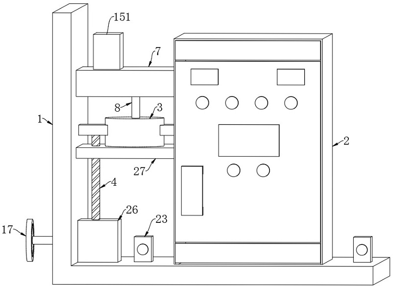
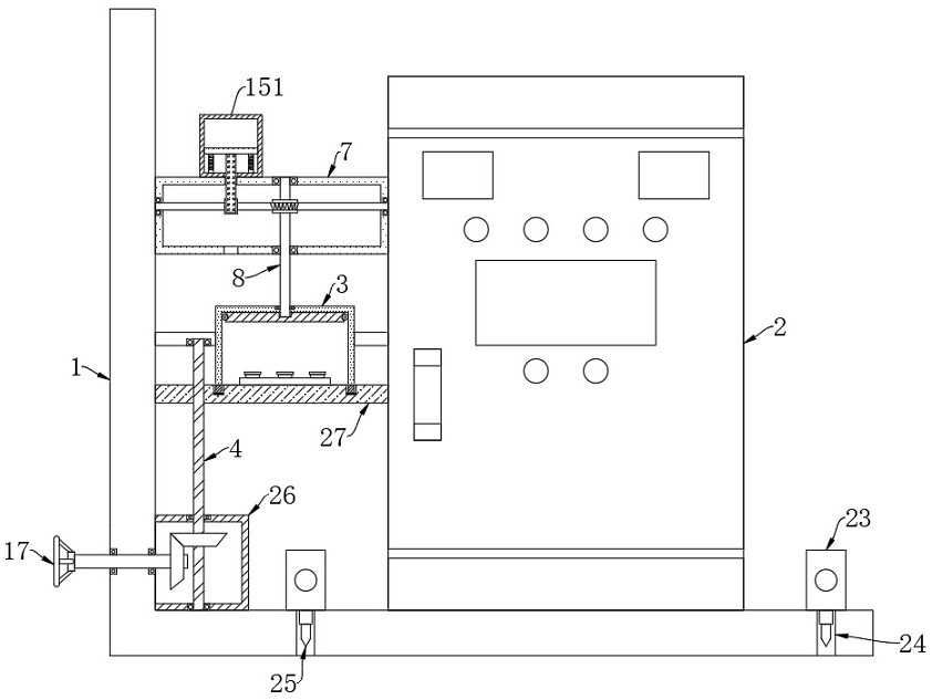
[0033] Such as Figure 1-8 As shown, a high-voltage and low-voltage power distribution cabinet with an anti-mis-touch protection structure includes a support base 1 and a cabinet body 2. Two cylinders 23 are arranged on the support base 1, and there are corresponding cylinders 23 on the support base 1. storage slot 24, the output end of the cylinder 23 extends into the storage slot 24 and is fixedly connected with the insertion rod 25, through the cooperation of the set cylinder 23 and the insertion rod 25, it is convenient for the staff to control the insertion rod 25 and the ground through the cylinder 23 , to ensure the stability of the placement of the entire device, and the storage slot 24 provided in addition can accommodate the insertion rod 25 when the device is moved later.

[0034] The cabinet body 2 is fixedly connected to the support base 1,...


PUM


Abstract

The invention belongs to the field of power distribution cabinets, and particularly relates to a high-low voltage power distribution cabinet with an anti-accidental-touch protection structure. The high-low voltage power distribution cabinetcomprises a supporting seat and a cabinet body, wherein the cabinet body is fixedly connected to the supporting seat, a protective cover is fixedly connected between the supporting seat and the cabinet body, a lead screw is rotatably connected to the supporting seat, the lower end of the protective cover is connected with a supporting plate in a matched mode, and the supporting plate is in threaded connection with the lead screw. According to the invention, by arranging a regulating mechanism, self-starting can be achieved in hot weather in summer; the self-transmission of a worm rod can be regulated and controlled by matching with a gear;under transmission of a worm gear, a rotating shaft can drive a closing plate to rotate automatically, and then a first opening and a second opening coincide automatically, so that automatic opening of a protective cover is achieved, and the complexity of manual opening is avoided; and the separating brake of the device is arranged on one side of the cabinet body, so that compared with a traditional mode of arranging the separating brake and the protective cover on the cabinet door, the device can effectively avoid mistaken touch when the cabinet door is opened and closed.

Description

technical field [0001] The invention belongs to the field of power distribution cabinets, in particular to a high and low voltage power distribution cabinet with an anti-mis-touch protection structure. Background technique [0002] Power distribution cabinets are divided into power distribution cabinets, lighting distribution cabinets, and metering cabinets, and are the final equipment of the power distribution system. The power distribution cabinet is the general name of the motor control center. The power distribution cabinet is used in the occasions where the load is relatively scattered and there are few circuits. The motor control center is used in the occasions where the load is concentrated and there are many circuits. The electrical energy distributed to the nearest load, this level of equipment should provide protection, monitoring and control of the load. [0003] At present, in order to quickly disconnect the power in an emergency, the existing outdoor high and l...

Claims


Application Information

Patent Timeline
IPC IPC(8): H02B1/50H02B1/30H02B1/32
CPCH02B1/30H02B1/32H02B1/505
Inventor 王红莉
Owner 王红莉
Why Eureka
Try Eureka