A lower splint structure for loudspeaker

A loudspeaker and splint technology, applied in the field of loudspeakers, can solve the problems of single heat dissipation, inability to conduct more effective heat dissipation, poor heat dissipation, etc., and achieve the effect of accelerated cooling

Active Publication Date: 2022-06-21
ZHEJIANG OUSAI ELECTRONICS CO LTD
View PDF10 Cites 0 Cited by
  • Summary
  • Abstract
  • Description
  • Claims
  • Application Information

AI Technical Summary

Problems solved by technology

[0003] In the traditional loudspeaker equipment, the heat dissipation of the loudspeaker mainly depends on the through holes opened on the basin frame for air exchange. This kind of heat dissipation method is relatively simple and cannot carry out more effective heat dissipation. Vibration achieves air exchange, and the same distance leads to poor heat dissipation. Now a speaker with a lower splint structure is proposed to dredge the air to improve heat dissipation efficiency

Method used


Image

  • A lower splint structure for loudspeaker
  • A lower splint structure for loudspeaker
  • A lower splint structure for loudspeaker

Examples


Embodiment

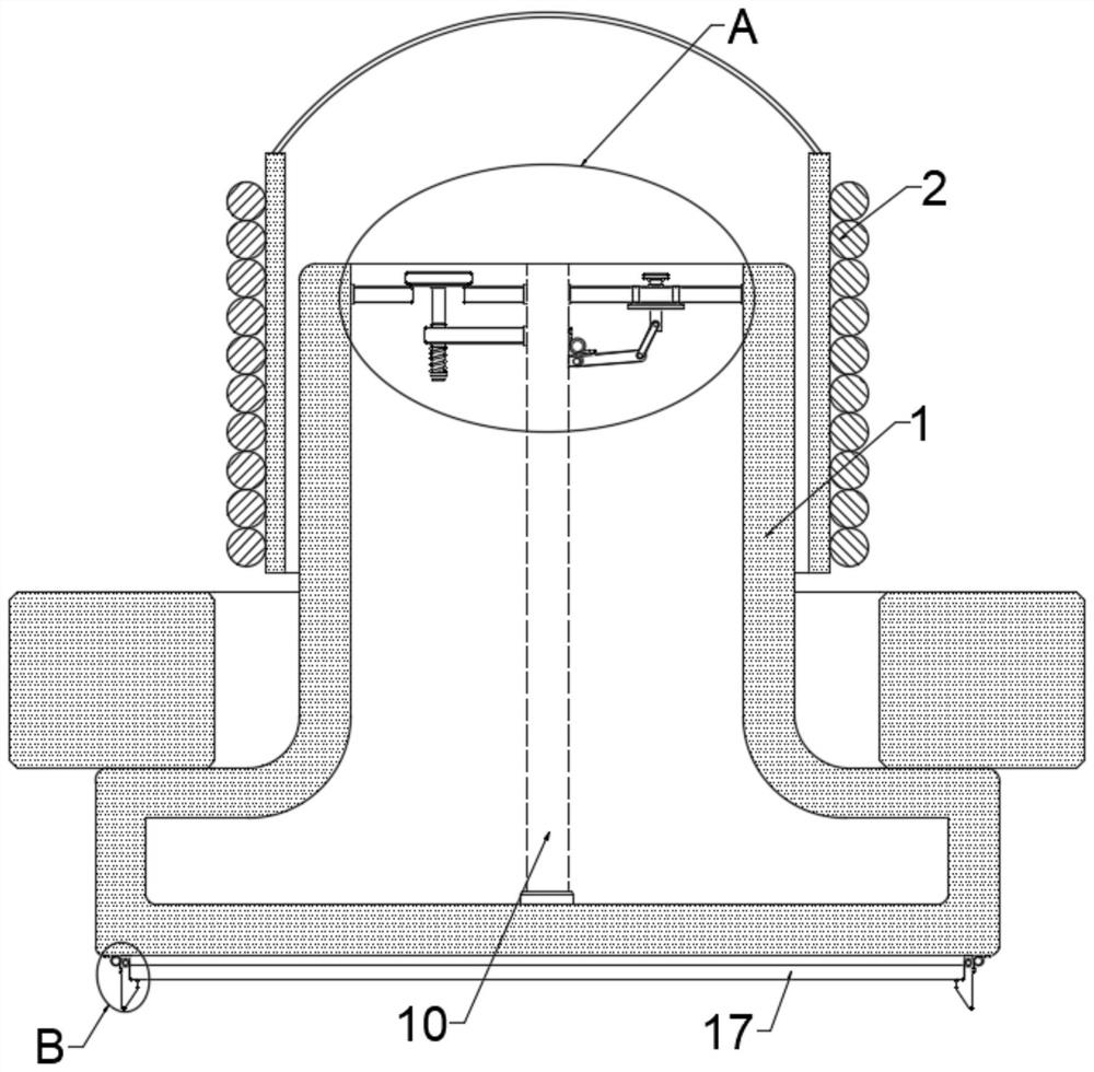
[0027] Example: a lower plywood structure for loudspeakers, such as Figure 1-Figure 4 As shown, the speaker is inserted in the voice coil 2 with a lower splint structure and used to fix the permanent magnet, including:

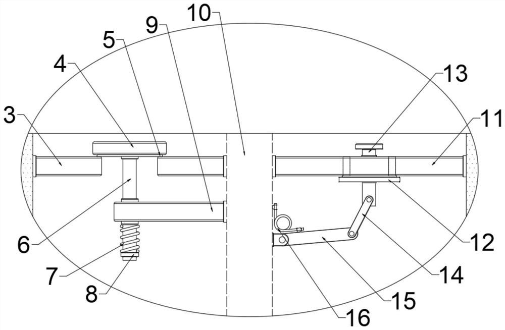
[0028] The lower splint 1, the lower splint 1 is movably connected with the voice coil 2, the lower splint 1 is internally connected and is fixedly installed with a sealing plate 10, which divides the lower splint 1 into two independent and conducting chamber;

[0029] Air intake mechanism, the air intake mechanism is arranged in one of the chambers to suck outside air into the space formed between the voice coil 2 and the lower plate 1 when the voice coil 2 vibrates upwards Inside;

[0030] an exhaust mechanism, the exhaust mechanism is arranged in the other chamber so that the hot air in the space formed between the voice coil 2 and the lower plate 1 is exhausted when the voice coil 2 vibrates downward;

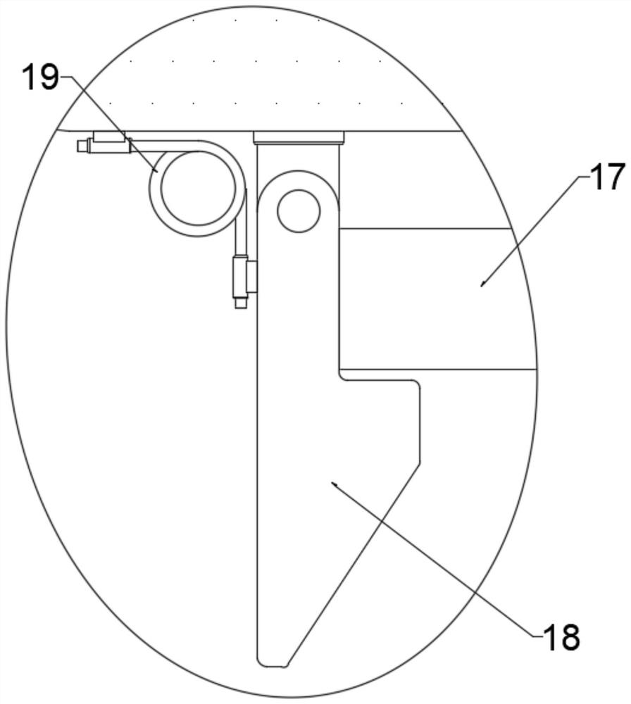
[0031] A filter assembly, the filter assembly is ...


PUM


Abstract

A lower splint structure for a loudspeaker, belonging to the field of loudspeakers; the lower splint structure for a speaker is inserted into a voice coil and used to fix a permanent magnet, including a lower splint, which is movably connected with the voice coil, and the The inside of the lower splint is connected and fixedly installed with a sealing plate, which divides the lower splint into two independent and conductive chambers; an air intake mechanism, the air intake mechanism is arranged in one of the chambers It is used to suck the outside air into the space formed between the voice coil and the lower splint when the voice coil vibrates upward; the exhaust mechanism is arranged in the other cavity to When the voice coil vibrates downward, the hot air in the space formed between the voice coil and the lower splint is discharged; the filter assembly is arranged at the lower part of the lower splint, and the filter assembly is used It is used to purify the air entering into the lower clamping plate to absorb dust in the air entering into the lower clamping plate.

Description

technical field [0001] The invention belongs to the technical field of loudspeakers, and in particular relates to a lower clamp plate structure for loudspeakers. Background technique [0002] Speaker splint. The material is soft iron, that is, pure iron, also known as electrical iron. The main feature is magnetic permeability, but there is no residual magnetism, that is, after the magnetic field disappears, its magnetism disappears immediately. The purity and quality of this iron directly affect the efficiency of the speaker. For important parameters such as nonlinear distortion, the thickness of the splint affects the stroke of the speaker. The T-iron splint of a long-stroke speaker is particularly thick, that is, parallel and uniform magnetic lines of force can be cut throughout the entire stroke of the voice coil. The smaller the gap between the splint and the center column of the T iron, the smaller the power required for the movement of the voice coil, and the higher t...

Claims


Application Information

Patent Timeline
Patent Type & Authority Patents(China)
IPC IPC(8): H04R9/02H04R9/04H04R9/06H04R1/12H05K7/20
CPCH04R9/022H04R9/025H04R9/04H04R9/06H04R1/12H05K7/20145
Inventor 钱天翼
Owner ZHEJIANG OUSAI ELECTRONICS CO LTD
Why Eureka
Try Eureka