
Method and device for operating a braking system, and braking system

A braking system and braking force technology, applied in the direction of braking transmission, transportation and packaging, brakes, etc., can solve problems such as braking force auxiliary adaptation, and achieve the effect of pressure reduction and prevention

Pending Publication Date: 2021-08-10
ROBERT BOSCH GMBH
View PDF0 Cites 0 Cited by
  • Summary
  • Abstract
  • Description
  • Claims
  • Application Information

AI Technical Summary

Problems solved by technology

However, external factors may also cause the dynamics of the brake assist to be adapted

Method used


Image

  • Method and device for operating a braking system, and braking system
  • Method and device for operating a braking system, and braking system
  • Method and device for operating a braking system, and braking system

Examples


Embodiment Construction

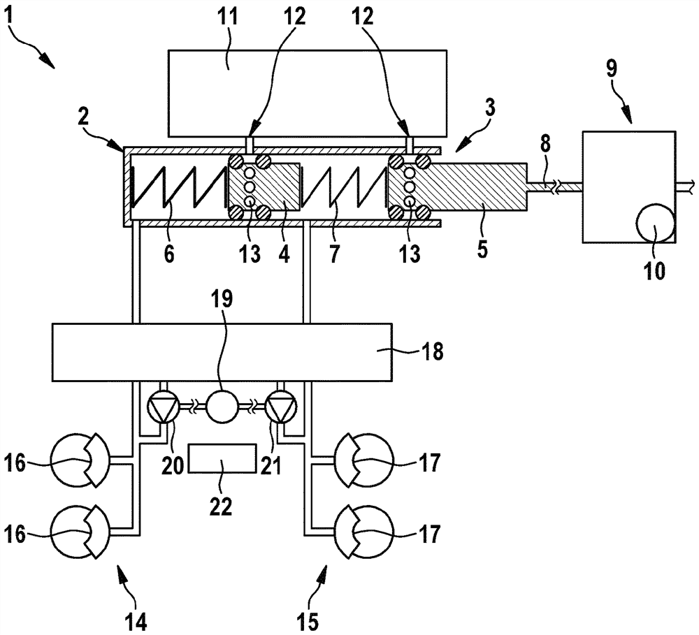
[0018] figure 1 An advantageous braking system 1 of a motor vehicle, which is not shown in detail here, is shown in a simplified illustration. figure 1 The dimension ratios in are chosen for simplicity reasons only, but they are not realistic.

[0019] The brake system 1 has a master brake cylinder 2 in which a piston 3 configured as a tandem piston is mounted so that it can move axially. The tandem piston has a first piston part 4 and a second piston part 5 , wherein the piston part 4 is displaceable against the force of a first spring element 6 supported on the end side of the main brake cylinder 2 , and the The second piston part 5 is displaceable relative to a spring element 7 which is supported at the other end on the first piston part 4 . Piston 3 is coupled via a piston rod 8 to an electromechanical brake booster 9 . The brake booster 9 has a controllable electric motor 10, which is coupled to the piston rod 8 via a gear mechanism, in order to move the piston 3 into ...


PUM


Abstract

The invention relates to a method for operating a braking system (1) of a motor vehicle, the braking system (1) comprising a master brake cylinder (2) having a slidably mounted piston (3) and comprising an electromechanical brake booster (9), which is mechanically coupled to the piston (3) in order to slide the piston in the master brake cylinder (2) to build up and reduce pressure in an associated brake circuit (14, 15), the return speed of the piston (3) being reduced depending on the operating state of the motor vehicle, particularly in order to minimize noise. According to the invention, the motor vehicle is monitored for a pressure build-up demand and the reduction of the return speed is lifted if a pressure build-up demand is detected.

Description

technical field [0001] The invention relates to a method for operating a brake system of a motor vehicle, wherein the brake system has a brake master cylinder and an electromechanical brake booster, wherein the brake master cylinder has a displaceably mounted and wherein the electromechanical brake booster is mechanically coupled to the piston for moving the piston in the master brake cylinder for pressure build-up and pressure in the associated brake circuit Reduction, whereby the return speed of the piston is reduced or limited depending on the operating state of the motor vehicle, in particular to minimize noise. [0002] Furthermore, the invention relates to a device for operating a braking system configured as described above and to such a braking system. Background technique [0003] Methods and devices of the type mentioned at the outset, as well as braking systems, are known from the prior art. The increasing electrification of motor vehicles also concerns the brak...

Claims


Application Information

Patent Timeline
IPC IPC(8): B60T8/48B60T13/74
CPCB60T8/4872B60T8/4845B60T13/745
Inventor A·卡默尔D·齐普里希F·廷施密特M·施马尔霍尔茨
Owner ROBERT BOSCH GMBH
Learn More