Sewage upper-layer floating garbage recovery equipment
A technology for recycling equipment and garbage, which is applied in the direction of filtration circuit, filtration separation, separation method, etc., can solve the problems of low practicability, reduce the efficiency and inconvenience of recycling and processing sewage floating garbage, and achieve the effect of improving the effect of recycling and processing
- Summary
- Abstract
- Description
- Claims
- Application Information
AI Technical Summary
Problems solved by technology
Method used
Image
Examples
Embodiment 1
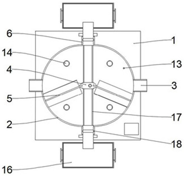
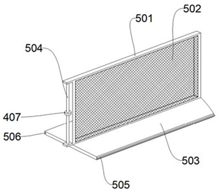
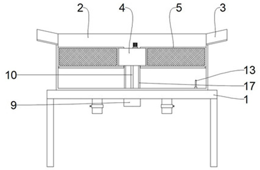
[0033] See figure 1 , 3 5, 6, a sewage upper floating waste recovery device, including receiving case 2, driving assembly 4, and collecting assembly 16, the receiving case 2 is disposed on the base 1, and the housing box 2 is provided with an inlet port 3 and the water port. 6. The bids of the housing case 2 are arranged semi-circular, and the number of water port 6 is set to two and the water port 6 is disposed at the end position of the semi-circular box body. The lifting valve 8 that controls the open or off, the drive assembly 4 is disposed in the inner cavity by the strut 10, in the present embodiment, the strut 10 is provided as a hollow rod, the base 1 The bottom portion is provided with a power source 9, and a console 11 is provided on the base 1, the drive assembly 4 can be connected to the power supply 9 and the console 11 in the strut 10, and the control panel 12 is provided on the console 11. To the control drive assembly 4 is started or closed, the drive assembly 4 is...
Embodiment 2
[0039] See figure 1 , 6 On the basis of the first example, the lifting valve 8 includes a valve body 801, a drain groove 802 disposed on the end portion of the valve body 801 and a connecting plate 803 disposed on both sides of the valve body 801, the housing box 2. A scalable member 7 is provided at the corresponding position corresponding to the lift valve 8, the pilot groove 802 is inclined, and the drain groove 802 functions to direct sewage and floating garbage and fall into the collection assembly 16, the scalable member 7 One end is connected to the connecting plate 803, which can be selected as an electric telescopic rod, a pneumatic telescopic rod, or the like, can be moved in a vertical direction in the water port 6.
[0040] Preferably, please refer to figure 1 , 7 In order to improve the connection sealing of the valve body 801 and the water port 6, a sealing groove 18 is provided on the inner wall of the outlet 6, and the valve body 801 is provided on both sides of th...
Embodiment 3
[0042] See figure 1 , 8 On the basis of the first and second, the collecting assembly 16 includes an outer frame 1601 and an interior frame 1604 disposed at the outer frame 1601 port, and the outer frame 1601 is provided with a drain pipe 1602, the interior frame 1604 The floating waste in the sewage is filtered down and only allowed to fall into the outer frame 1601 in the lumen, and the filtering function of the inner frame 1604 can be realized by providing a filter or filter hole at the bottom of the interior frame 1604.
[0043] See Figure 8 , 9 In order to facilitate the convenience of the internal frame 1604 from the outer frame 1601 port, a placement slot 1603 is provided at both sides of the outer frame 1601, and a connecting rod 1605 is provided at the corresponding position on both sides of the inner frame 1604, the connection. The rod 1605 is placed in the placement slot 1603, and the lift rod 1606 is connected at one end of the connecting rod 1605.
[0044] Working pri...
PUM
 Abstract
Description
Claims
Application Information
 - R&D
- Intellectual Property
- Life Sciences
- Materials
- Tech Scout
- Unparalleled Data Quality
- Higher Quality Content
- 60% Fewer Hallucinations
Browse by: Latest US Patents, China's latest patents, Technical Efficacy Thesaurus, Application Domain, Technology Topic, Popular Technical Reports.
© 2025 PatSnap. All rights reserved.Legal|Privacy policy|Modern Slavery Act Transparency Statement|Sitemap|About US| Contact US: help@patsnap.com


