
An all-round painting equipment for castings

A kind of painting equipment and all-round technology, which is applied in the direction of painting booth, spraying device, coating, etc., can solve the problems of cumbersome operation, incomplete painting, low painting efficiency, etc., and achieve the effect of high work efficiency and convenient operation and use

Active Publication Date: 2021-09-24
潍坊市工程技师学院
View PDF0 Cites 0 Cited by
  • Summary
  • Abstract
  • Description
  • Claims
  • Application Information

AI Technical Summary

Problems solved by technology

[0003] When painting some cylindrical castings, the traditional painting method is generally to place them vertically, and then use the painting device to rotate and paint the parts. If the side is sprayed, the upper and lower sides of the casting cannot receive the spray paint, and the spray paint is not complete. If you want to carry out full-scale spray paint, you need to spray paint again on the upper and lower sides. The operation is cumbersome and the work efficiency of spray paint is low.

Method used


Image

  • An all-round painting equipment for castings
  • An all-round painting equipment for castings
  • An all-round painting equipment for castings

Examples


Embodiment 1

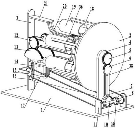
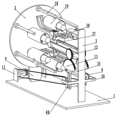
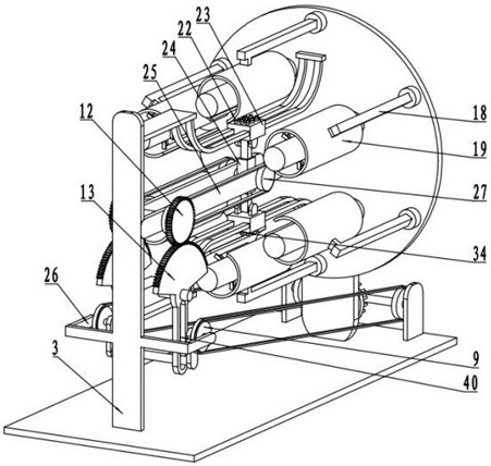
[0030] see Figure 1-8 , an all-round painting equipment for castings, including a bottom plate 1, and also includes:

[0031] The fixed rod 4 is fixedly arranged on one side of the bottom plate 1, the side of the fixed rod 4 is rotatably connected to the mounting plate 2, and the bottom plate 1 on the side of the mounting plate 2 away from the fixed rod 4 is fixedly connected to the mounting rod 3;

[0032] The conversion mechanism 36 arranged on one side of the installation disk 2 includes a plurality of installation arms 18, the installation arms 18 are fixedly connected with the installation disk 2, and one side of the installation arm 18 is fixedly connected with an arc-shaped cylinder 19. A plurality of electric telescopic rods 31 are fixedly connected to the inner wall of the arc-shaped cylinder 19, and one end of the electric telescopic rods 31 is rotatably connected to a drive roller 33, and one axial side of the drive roller 33 is provided with an installation motor,...

Embodiment 2

[0037] see Figure 1-8 , the other content of this embodiment is the same as that of Embodiment 1, the difference is that: the drive assembly 38 includes a transmission gear 5, the transmission gear 5 is rotationally connected with the fixed rod 4, and one end of the rotating shaft of the transmission gear 5 is connected to the mounting plate 2 The rotating shaft is fixedly connected, the transmission gear 5 side is provided with an incomplete gear 6, and the rotating shaft axial side of the incomplete gear 6 is provided with a driving motor 32, and the driving motor 32 is fixedly connected with the fixed rod 4, and the driving motor 32 One end of the output shaft is fixedly connected to one end of the rotating shaft of the incomplete gear 6, and the incomplete gear 6 is provided with a drive disc 7 on the side away from the transmission gear 5, and the drive disc 7 is connected to the fixed rod 4 in rotation, and the drive disc 7 is connected to the incomplete gear. The rotat...


PUM


Abstract

The invention discloses an all-round painting equipment for castings, which relates to the technical field of painting equipment, including a bottom plate, and further includes: a fixed rod arranged on one side of the bottom plate, a mounting plate is arranged on one side of the fixed rod, and the mounting plate is far away from the side of the fixed rod There is a mounting rod on the bottom plate, and the paint spraying and drying mechanism is arranged on one side of the conversion mechanism, including the fixed beams arranged on both sides of the mounting rod. The end of the fixed beam is far away from the mounting rod. An elastic piece is arranged in the groove, a piston rod is arranged on one side of the elastic piece, and a mounting slide rail is provided on a side of the piston rod far away from the installation cylinder. A dryer and a paint sprayer are respectively arranged on the end faces of the installation blocks on the upper and lower sides of the installation cylinder; the drive mechanism arranged on one side of the fixed rod includes a drive assembly and a transmission assembly for driving the conversion mechanism and the paint spray drying mechanism.

Description

technical field [0001] The invention relates to the technical field of painting equipment, in particular to an all-round painting equipment for castings. Background technique [0002] In the process of casting production, the producer often sprays paint on the surface of the casting according to the demand. On the one hand, it is for the beauty of the casting surface. On the other hand, the paint film on the casting can protect the casting and effectively prevent the surface of the casting. Oxidized and rusted. [0003] When painting some cylindrical castings, the traditional painting method is generally to place them vertically, and then use the painting device to rotate and paint the parts. If the side is sprayed, the upper and lower sides of the casting cannot receive the spray paint, and the spray paint is not complete. If you want to carry out full-scale spray paint, you need to spray paint again on the upper and lower sides. The operation is cumbersome and the work ef...

Claims


Application Information

Patent Timeline
Patent Type & Authority Patents(China)
IPC IPC(8): B05B16/20B05B13/02B05B13/04B05B15/68B05D3/04
CPCB05B13/0228B05B13/041B05D3/0413B05B15/68B05B16/20
Inventor 赵福鹏赵帅帅王学美
Owner 潍坊市工程技师学院
Learn More