
Pipeline inner wall maintenance machine with cleaning and paint spraying functions

A technology for maintaining machines and pipes, which is applied in spray booths, cleaning hollow objects, cleaning methods and utensils. the effect of interference

Inactive Publication Date: 2021-03-05
安徽麦壳科技有限公司
View PDF7 Cites 1 Cited by
  • Summary
  • Abstract
  • Description
  • Claims
  • Application Information

AI Technical Summary

Problems solved by technology

[0007] The inventor currently has a batch of short pipes that need to be maintained for pipelines, and different anti-corrosion paints must be applied to the inner and outer walls, so dip-dyeing paint cannot be used; and these short pipes have been used, and there will be some attachments on the inner wall. The actual anti-corrosion effect is not good, so the inner wall needs to be cleaned and treated
The usual way is to use cleaning equipment to clean the inner wall of the pipe, and then use spraying equipment to paint the inner wall, that is, two independent equipment are required, and for the case of a large number and short pipes, this more troublesome to operate

Method used


Image

  • Pipeline inner wall maintenance machine with cleaning and paint spraying functions
  • Pipeline inner wall maintenance machine with cleaning and paint spraying functions
  • Pipeline inner wall maintenance machine with cleaning and paint spraying functions

Examples


Embodiment 1

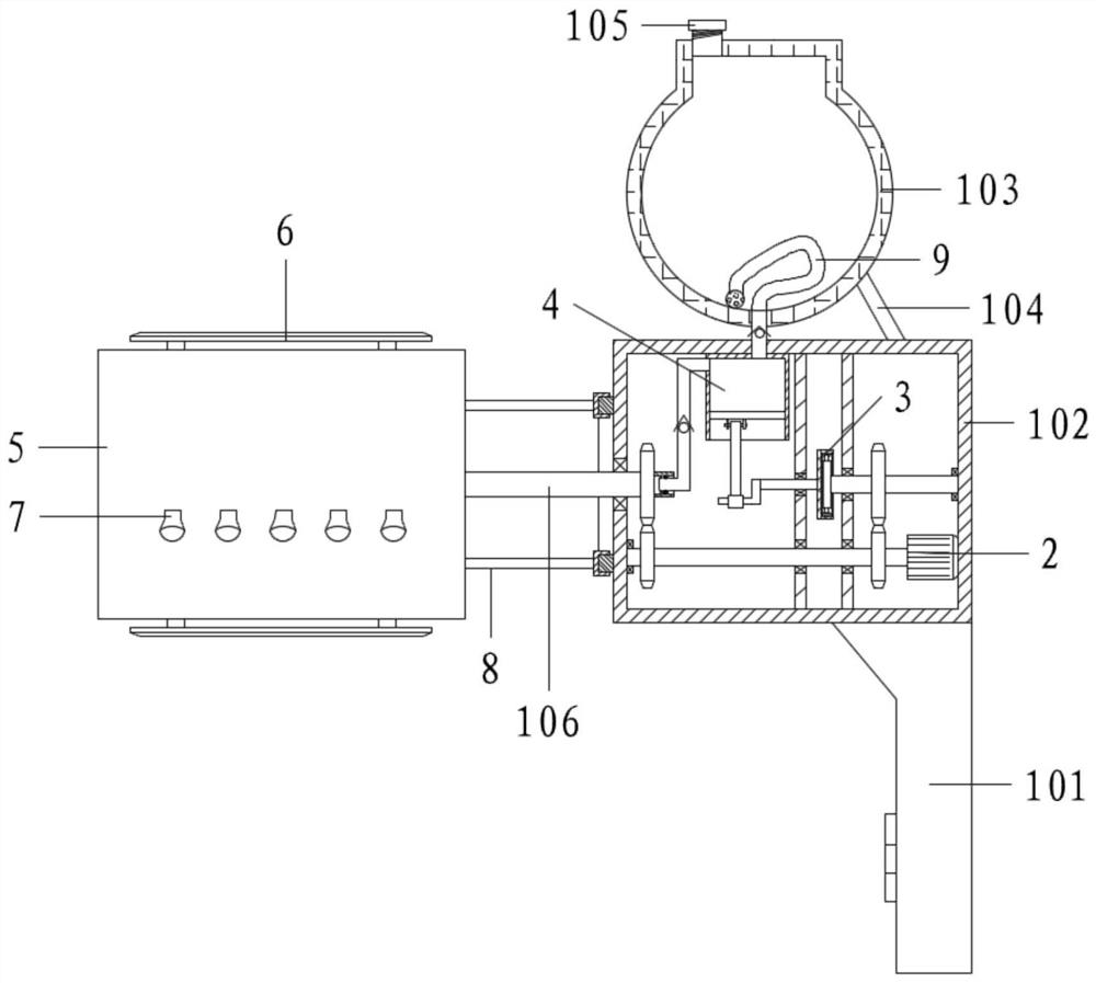
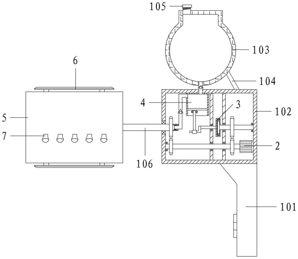
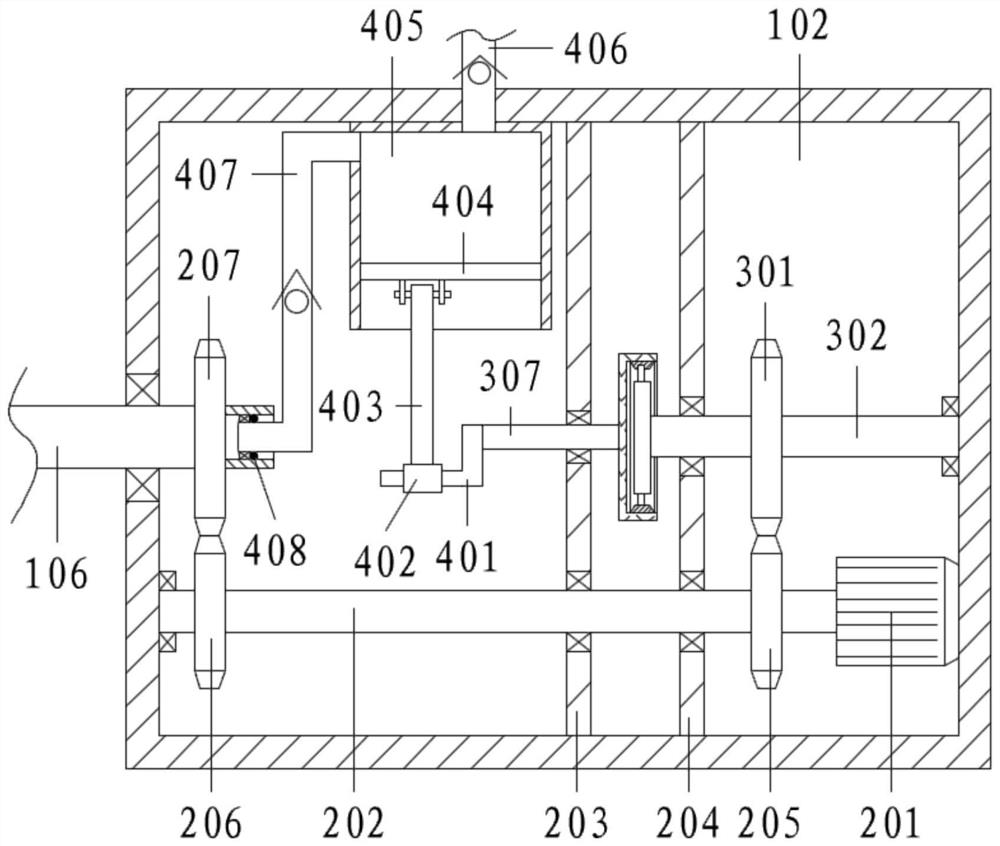
[0066] Referring to the accompanying drawings, a pipeline inner wall maintenance machine with cleaning and painting functions includes a handle 101, a power box 102, a paint storage tank 103, a fixed rod 104, a sealing cover 105 and a main shaft 106;

[0067] The top of the handle 101 is fixed with a power box 102; the paint storage tank 103 is connected above the power box 102 through a fixed rod 104, and the top of the paint storage tank 103 is screwed with a sealing cover 105;

[0068] The bottom of the power box 102 is provided with a drive assembly 2, and the drive assembly 2 is provided with a servo motor 201 to drive; the handle 101 is equipped with a battery for powering the servo motor 201, and is provided with a switch for controlling the forward and reverse of the servo motor 201; the top of the power box 102 The self-switching assembly 3 and the exhaust assembly 4 are provided. The exhaust assembly 4 is located on the left side of the self-switching assembly 3; the ...

Embodiment 2

[0070] Referring to the accompanying drawings, a pipeline inner wall maintenance machine with cleaning and painting functions includes a handle 101, a power box 102, a paint storage tank 103, a fixed rod 104, a sealing cover 105 and a main shaft 106;

[0071] The top of the handle 101 is fixed with a power box 102; the paint storage tank 103 is connected above the power box 102 through a fixed rod 104, and the top of the paint storage tank 103 is screwed with a sealing cover 105;

[0072] The bottom of the power box 102 is provided with a drive assembly 2, and the drive assembly 2 is provided with a servo motor 201 to drive; the handle 101 is equipped with a battery for powering the servo motor 201, and is provided with a switch for controlling the forward and reverse of the servo motor 201; the top of the power box 102 The self-switching assembly 3 and the exhaust assembly 4 are provided. The exhaust assembly 4 is located on the left side of the self-switching assembly 3; the ...

Embodiment 3

[0096] In the above embodiments, the processing head 5 is only supported by the main shaft 106, and the main shaft 106 has a relatively large load.

[0097] Therefore, on the basis of the above-mentioned embodiment,

[0098] It also includes a reinforcement assembly 8; the reinforcement assembly 8 includes a pole 801, a slider 802 and an annular slide rail 803;

[0099] The outer wall on the left side of the power box 102 is fixed with an annular slide rail 803, and the annular slide rail 803 is coaxially arranged with the main shaft 106; the right side of the outer cylinder 501 is connected with a slider 802 through a strut 801, and the slider 802 and the annular slide rail 803 slide connect.

[0100] Specifically, when the outer cylinder 501 rotates, the sliding block 802 is also synchronously moved along the circular slide rail 803 through the support rod 801, and the support for the processing head 5 is enhanced.


PUM


Abstract

The invention relates to the technical field of short pipe inner wall cleaning and paint spraying, in particular to a pipeline inner wall maintenance machine with cleaning and paint spraying functions. The pipeline inner wall maintenance machine comprises a grab handle, a power box, a paint storage tank, a fixed rod, a sealing cover and a spindle, wherein a driving component is arranged at the lower part of the power box and is provided with a servo motor for driving; a self-switching component and a pumping component are arranged at the upper part of the power box, and the pumping component is located at the left side of the self-switching component; the right side of the self-switching component is matched with the driving component, and the left side of the self-switching component is matched with the pumping component; the spindle is arranged leftwards on the power box, and a machining head is arranged at the outer end of the spindle and provided with a cleaning component and a paint spraying component; and one end of the pumping component is communicated with the paint storage tank, and the other end of the pumping component is matched with the paint spraying component. The device is simple and convenient to use, the cleaning function and the paint spraying function can be automatically achieved only by controlling the servo motor to rotate forwards and backwards and beingmatched with the self-switching component, and interference between the cleaning function and the paint spraying function is avoided.

Description

technical field [0001] The invention relates to the technical field of cleaning and spraying the inner wall of a short pipe, in particular to a maintenance machine for the inner wall of a pipe with the functions of cleaning and painting. Background technique [0002] A pipeline is a device used to transport gas, liquid or fluid with solid particles connected by pipes, pipe connectors and valves. Usually, after the fluid is pressurized by blowers, compressors, pumps and boilers, it flows from the high-pressure part of the pipeline to the low-pressure part, and it can also be transported by the pressure or gravity of the fluid itself. Pipes are widely used, mainly in water supply, drainage, heat supply, gas supply, long-distance transportation of oil and natural gas, agricultural irrigation, hydraulic engineering and various industrial devices. [0003] Most of the pipelines for transporting oil and gas are located in complex soil environments, and the transported media are m...

Claims


Application Information

Patent Timeline
Patent Type & Authority Applications(China)
IPC IPC(8): B05B16/25B05B13/06B05D3/00B08B9/027
CPCB05B13/0636B05D3/002B08B9/027B05B16/25
Inventor 张立双
Owner 安徽麦壳科技有限公司
Learn More