Cylindrical diaphragm

A diaphragm and cylindrical technology, which is applied in the field of aircraft liquid storage and management, can solve the problem that the metal diaphragm tank cannot meet the requirements of cylindrical installation space, etc., and achieve the effects of being beneficial to attitude control, stable center of mass and stable pressure difference.

Active Publication Date: 2021-08-13
SHANGHAI INST OF SPACE PROPULSION
View PDF9 Cites 1 Cited by
  • Summary
  • Abstract
  • Description
  • Claims
  • Application Information

AI Technical Summary

Problems solved by technology

[0003] The purpose of the present invention is to provide a liquid propellant extrusion-isolating device for aircraft power system, which solves the problem that the metal diaphragm tank in the prior art cannot meet the requirement of cylindrical installation space

Method used

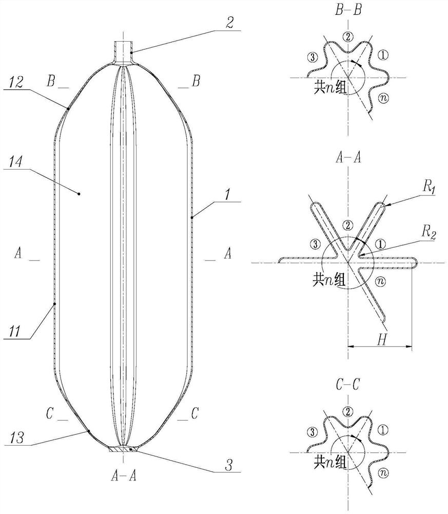

Image

  • Cylindrical diaphragm
  • Cylindrical diaphragm
  • Cylindrical diaphragm

Examples


Embodiment 1

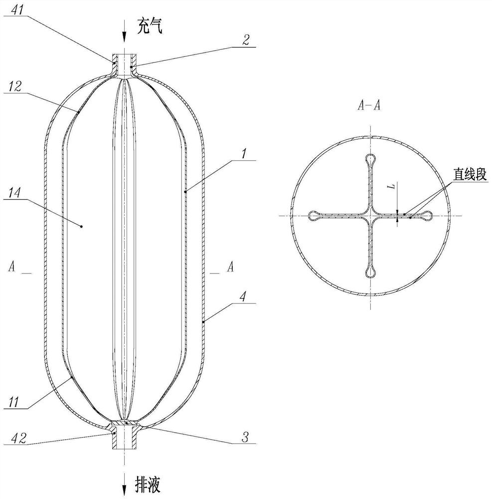
[0036] Such as figure 2 As shown, a propellant tank using a cylindrical diaphragm provided by the present invention, the diaphragm cylinder 1 is arranged in the inner cavity of the tank shell 4; The filling and deflation port 41 is sealed and connected, and the assembly joint 3 is fixedly connected with the filling and discharging port 42 of the storage tank shell 4; The inner walls of the tank housing 4 together form a liquid storage chamber 5 .

[0037] Specifically, in this embodiment, the diaphragm cylinder 1 is made of metal material with a wall thickness of 1 mm.

[0038] Specifically, in this embodiment, the number of "∩"-shaped structures of the diaphragm cylinder 1 is four.

[0039] Specifically, in this embodiment, the two straight line segments of the "∩"-shaped structure of the diaphragm cylinder 1 are parallel, and the distance L is 1 mm.

[0040] Specifically, in this embodiment, the diaphragm cylinder 1 is connected to the inflation joint 2 and the installat...

Embodiment 2

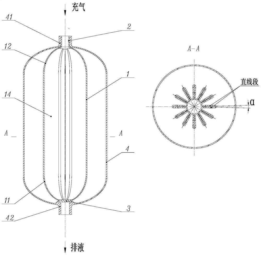
[0045] This embodiment is an improvement based on Embodiment 1, such as image 3 shown.

[0046] Specifically, in this embodiment, the diaphragm cylinder 1 is made of non-metallic material with a wall thickness of 2mm.

[0047] Specifically, in this embodiment, the number of "∩"-shaped structures of the diaphragm cylinder 1 is 12.

[0048] Specifically, in this embodiment, the angle between two straight line segments of the “∩”-shaped structure of the diaphragm cylinder 1 is α=3°.

[0049] Specifically, in this embodiment, the diaphragm cylinder 1 is glued to the inflation joint 2 and the installation joint 3 .

[0050] Specifically, in this embodiment, after the diaphragm cylinder 1 is inflated and fully expanded from the inside to the outside, the profile of the cylinder body 11 is cylindrical, and the profiles of the first head 12 and the second head 13 are both semi-cylindrical. Ellipsoid.

Embodiment 3

[0052] This embodiment is an improved manner based on Embodiment 1 or Embodiment 2.

[0053] Specifically, in this embodiment, after the diaphragm cylinder 1 is inflated and fully expanded from the inside to the outside, the profile of the cylinder body 11 is cylindrical, the profile of the first head 12 is hemispherical, and the profile of the second head 13 is semi-ellipsoidal.


PUM


Abstract

The invention relates to a liquid propellant extrusion-isolation device of an aircraft power system, and discloses a cylindrical diaphragm which comprises a diaphragm barrel, an inflation connector and an assembly connector. The diaphragm cylinder is composed of a cylinder body, a first end socket and a second end socket which are in seamless connection, and an inner cavity formed by the inner surface of the diaphragm cylinder is used for being filled with pressurized gas. The gas charging connector is connected with the first end socket of the diaphragm cylinder at the polar hole, is communicated with the inner cavity of the diaphragm cylinder and is used for assembling the diaphragm and charging and discharging gas; and the assembly joint is connected with the second end socket of the diaphragm cylinder at the polar hole and is used for assembling the diaphragm. The problems that a metal diaphragm cannot achieve a cylindrical structure, and several existing cylindrical extrusion-isolation devices are large in deformation randomness, poor in sealing performance, large in weight and the like are solved, and the cylindrical diaphragm the beneficial effects of being wide in application range, high in reliability, good in safety and the like are achieved.

Description

technical field [0001] The invention relates to the field of storage and management of aircraft liquid, in particular to a cylindrical diaphragm. Background technique [0002] Diaphragm, as one of the important extrusion-isolation management devices of propellant tanks, is widely used in various aircraft power systems due to its high reliability and simple structure. It can realize gas-liquid isolation by itself, and realize the discharge of propellant through its own deformation under the action of gas pressure. According to the different materials, the diaphragm can be divided into metal diaphragm and non-metal diaphragm. Among them, the metal diaphragm can meet the long-term pre-packaging requirements of various aircraft systems, and at the same time, the regular deformation of its axisymmetric structure can ensure the stability of the center of mass of the system. However, the existing metal diaphragms can only adopt spherical, cone-cylindrical or ellipsoidal structure...

Claims


Application Information

Patent Timeline
Patent Type & Authority Applications(China)
IPC IPC(8): B64G1/40B64G1/22
CPCB64G1/402B64G1/22
Inventor 晏飞范凯王婷婷李敬业
Owner SHANGHAI INST OF SPACE PROPULSION
Why Eureka
Try Eureka