Mounting bracket, encoder connecting structure and motor

A technology for installing brackets and encoders, which is applied to structural connections, electromechanical devices, electrical components, etc., can solve the problems of poor verticality of the encoder and affect the work of the encoder, and achieve the effect of ensuring normal operation and meeting the requirements of installation space.

Pending Publication Date: 2022-01-25
GREE ELECTRIC APPLIANCES INC
View PDF4 Cites 0 Cited by
  • Summary
  • Abstract
  • Description
  • Claims
  • Application Information

AI Technical Summary

Problems solved by technology

[0007] The purpose of the present invention is to provide a mounting bracket, an encoder connection structure and a motor to solve the problem in the prior art that the encoder installed on the motor end cover is poorly perpendicular to the motor shaft, which affects the encoder's work. Problem; Many technical effects that the preferred technical solution in the many technical solutions provided by the present invention can produce are set forth in detail below

Method used


Image

  • Mounting bracket, encoder connecting structure and motor
  • Mounting bracket, encoder connecting structure and motor
  • Mounting bracket, encoder connecting structure and motor

Examples


Embodiment 1

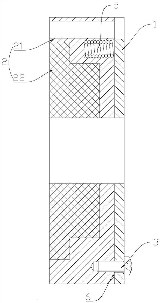
[0042] Such as Figure 3-Figure 6 As shown, this embodiment provides a mounting bracket, including a base 2 fixed to the assembly in the motor and a mounting part 1 with a mounting surface 11, wherein: there is a gap between the base 2 and the mounting part 1, The installation part 1 has a fixed part and a movable part, and the fixed part is locked with the base 2; adjusting the position of the movable part can change the distance between the movable part and the base 2, and then make the mounting surface 11 perpendicular to the motor shaft 402.

[0043] Wherein, the mounting part 1 includes a mounting plate, and a certain gap is set between the base 2 and the mounting plate, which can reserve a certain space for the position adjustment of the movable parts.

[0044] Typically, the "assembly" inside the motor is the rear endshield inside the motor, see Figure 7 As shown, the mounting bracket is fixed on the rear end cover, and the encoder is fixed on the mounting surface 11 ...

Embodiment 2

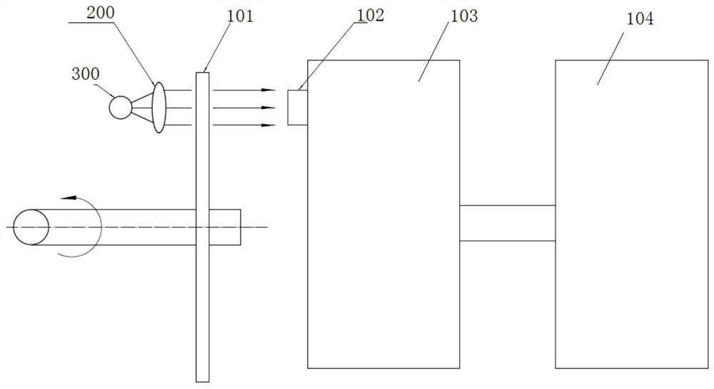
[0067] Such as figure 2 , The code disc 101 is directly locked on the motor shaft 402, and the heat and vibration generated by the motor winding and the brake are transmitted to the encoder 100, which is not conducive to the long-term stable operation of the encoder.

[0068] In view of the above problems, this embodiment has been improved on the basis of the above embodiments, see Figure 3-Figure 5 As shown, the base 2 of this embodiment includes a connected support plate 21 and a heat insulation plate 22, the support plate 21 is connected to the base 2, at least part of the heat insulation plate 22 can be in contact with the assembly parts in the motor to Prevent the vibration and / or heat of the motor from being transferred to the mounting surface 11 .

[0069]The function of the support plate 21 is to have a certain strength, which can better support the connection base 2 and the installation part 1, and ensure the overall structural strength of the installation bracket....

Embodiment 3

[0077] see Figure 7 As shown, this embodiment provides an encoder connection structure, including the above-mentioned installation bracket, the encoder is fixed on the installation surface 11, and the base 2 is fixedly connected with the assembly parts in the motor. see Figure 7 Specifically, the above-mentioned assembly is usually the rear end cover of the motor, and the base 2 is fixedly connected to the rear end cover of the motor.

[0078] The encoder connection structure of this embodiment can ensure that the encoder is perpendicular to the motor shaft 402 when it is fixed on the installation surface 11 by adjusting the installation bracket when there is an error in the size of the motor end cover, so that the encoder can meet the requirements for the installation space. requirements.


PUM


Abstract

The invention provides a mounting bracket, an encoder connecting structure and a motor, belongs to the field of electromechanical equipment, and aims to solve the problem that the work of an encoder is affected due to poor perpendicularity between the encoder mounted on a motor end cover and a motor shaft. The mounting bracket comprises a base fixed with an assembly part in the motor and a mounting part with a mounting surface, a gap exists between the base and the mounting part, the mounting part is provided with a fixed position and a movable position, and the fixed position is locked with the base; and the distance between the movable position and the base can be changed by adjusting the position of the movable position, so that the mounting surface is vertical to the motor shaft. According to the mounting bracket, encoder connecting structure and motor, the distance between the fixed position and the base is not changed, and the distance between the movable position and the base can be changed by adjusting the position of the movable position, so that the inclination of the mounting surface relative to the motor shaft can be adjusted, and the mounting surface is vertical to the motor shaft; and when the encoder is fixed on the mounting surface, the encoder can be ensured to be vertical to the motor shaft, and the normal work of the encoder is ensured.

Description

technical field [0001] The invention relates to the field of electromechanical technology, in particular to a mounting bracket, an encoder connection structure and a motor. Background technique [0002] The photoelectric encoder uses optical information as the carrier, through the grating secondary sensor to the photoelectric element, and converts the mechanical displacement into an electrical signal that can be calculated. Such as figure 1 as shown, figure 1 It is a schematic diagram of the working principle of the encoder in the prior art. The encoder is composed of code disc 101, detection grating 102, circuit body, chip 104, photoelectric conversion device 103 and other hardware and structural parts, as well as software programs. The light emitted by the light source 300 passes through the lens 200 reaches the code wheel 101. During the rotation of the code wheel 101, the moving grating and the fixed grating on the code wheel 101 are periodically turned on and off to p...

Claims


Application Information

Patent Timeline
Patent Type & Authority Applications(China)
IPC IPC(8): H02K11/20H02K11/22H02K5/00
CPCH02K11/20H02K11/22H02K5/00
Inventor 白文超陈飞龙李峰岩吉扬宏
Owner GREE ELECTRIC APPLIANCES INC
Why Eureka
Try Eureka