
Winding equipment for electrolytic copper foil production

A technology of electrolytic copper foil and equipment, which is applied in the field of winding equipment for electrolytic copper foil production, can solve the problems of manual removal, automatic rotation, and influence on the winding of electrolytic copper foil, so as to ensure the quality of winding and increase the cleaning work Effect

Active Publication Date: 2021-08-13
拓楚(江苏)电子科技有限公司
View PDF7 Cites 6 Cited by
  • Summary
  • Abstract
  • Description
  • Claims
  • Application Information

AI Technical Summary

Problems solved by technology

[0003] However, the current winding equipment for electrolytic copper foil production is directly wound on the outside of the winding drum after the electrolytic copper foil is produced, but there may be dust and other fine particles in the workshop due to various reasons. Once there is dust, When the fibers fall on the surface of the electrolytic copper foil, they will stick to the surface. After being corroded, the spots where the dust and fibers fall will gradually become black spots over time, which seriously affects the quality of the electrolytic copper foil. Reeling quality, and the current reel used for reeling electrolytic copper foil is directly set on the outside of the reeling rod, so that the reel may automatically rotate during the reeling process, which will affect the electrolytic copper foil The volume is retracted, and it needs to be removed manually when unloading, which is time-consuming and laborious

Method used


Image

  • Winding equipment for electrolytic copper foil production
  • Winding equipment for electrolytic copper foil production
  • Winding equipment for electrolytic copper foil production

Examples


Embodiment Construction

[0033] In order to make it easy to understand the technical means, creation features, achieved goals and effects of the present invention, the present invention will be further described below with reference to the specific embodiments.

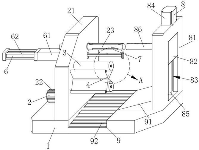
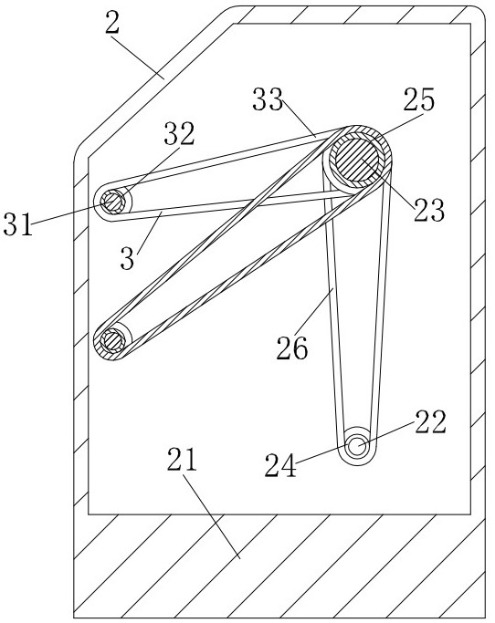
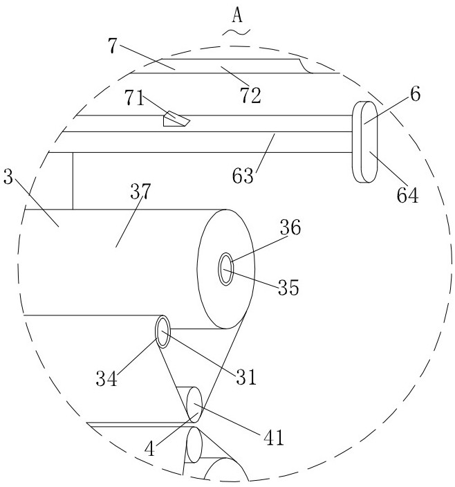
[0034] like Figure 1-Figure 11 As shown, a retracting device for electrolytic copper foil production according to the present invention includes a base 1, a retracting structure 2 is installed on the base 1, a cleaning structure 3 is installed on the retracting structure 2, and the A resisting structure 4 is installed on the retracting structure 2, and a limiting structure 5 is installed on the retracting structure 2. A pushing structure 6 is arranged on the retracting structure 2, and a fixing structure 7 is arranged on the retracting structure 2. , A discharge structure 8 is installed on the base 1, and a discharge structure 9 is arranged on the discharge structure 8.

[0035] Specifically, the retracting structure 2 includes a fixed base...


PUM


Abstract

The invention relates to the technical field of electrolytic copper foil production and processing, in particular to winding equipment for electrolytic copper foil production. The winding equipment comprises a base, a winding structure is mounted on the base, a cleaning structure is mounted on the winding structure, an abutting structure is mounted on the winding structure, and a limiting structure is further mounted on the winding structure. A pushing structure is arranged on the winding structure, a fixing structure is arranged on the winding structure, an unloading structure is installed on the base, and a pouring structure is arranged on the unloading structure; and when the winding structure conducts winding work, the cleaning structure can be synchronously driven to work, through work of the cleaning structure, the two faces of an electrolytic copper foil can be finely wiped in the manner that wiped cloth is wound, the problem of repeated wiping does not exist, the cleaning work on the surface of the electrolytic copper foil is increased, and the winding quality of the electrolytic copper foil is ensured.

Description

technical field [0001] The invention relates to the technical field of electrolytic copper foil production and processing, in particular to a winding device for electrolytic copper foil production. Background technique [0002] Electrolytic copper foil is an important material for the manufacture of copper clad laminates (CCL), printed circuit boards (PCB), and lithium-ion batteries. During the production and processing of electrolytic copper foil, in order to facilitate transportation and storage in the later stage, the produced electrolytic copper foil is generally rolled up on the outside of the reel for packaging. This process requires special winding equipment for electrolytic copper foil to operate. [0003] However, the current winding equipment for electrolytic copper foil production is directly wound on the outside of the winding drum after the electrolytic copper foil is produced, but there may be dust and other fine particles in the workshop due to various reason...

Claims


Application Information

Patent Timeline
IPC IPC(8): B65H18/10B65H19/30B65H18/02B08B1/02
CPCB65H18/10B65H19/30B65H18/026B65H2701/1133B65H2701/173B08B1/20
Inventor 徐龙廷
Owner 拓楚(江苏)电子科技有限公司
Learn More