
Device for automatically protecting air suction end of turbine to guarantee normal work

A turbine and automatic technology, applied in the field of turbines, can solve problems such as turbine damage, affecting air intake, collisions, etc.

Inactive Publication Date: 2021-08-13
何梓昕
View PDF0 Cites 0 Cited by
  • Summary
  • Abstract
  • Description
  • Claims
  • Application Information

AI Technical Summary

Problems solved by technology

[0005] Aiming at the deficiencies of the prior art, the present invention provides a device that automatically protects the suction end of the turbine to ensure normal operation. It can automatically clean and collect the surface of the filter plate at the lower end of the turbine. When the turbine is damaged, the advantage of automatically alarming the outside solves the problem that when the turbine inhales external air, it often needs to pass through the filter plate to block the particles in the air, but when the surface of the filter plate is easy to accumulate particles , affecting the intake of air. At the same time, when the filtering effect of the filter plate becomes poor, it is easy to cause the particles to collide with the turbine, causing the problem of wear of the turbine.

Method used


Image

  • Device for automatically protecting air suction end of turbine to guarantee normal work
  • Device for automatically protecting air suction end of turbine to guarantee normal work
  • Device for automatically protecting air suction end of turbine to guarantee normal work

Examples


Embodiment Construction

[0023] The following will clearly and completely describe the technical solutions in the embodiments of the present invention with reference to the accompanying drawings in the embodiments of the present invention. Obviously, the described embodiments are only some, not all, embodiments of the present invention. Based on the embodiments of the present invention, all other embodiments obtained by persons of ordinary skill in the art without making creative efforts belong to the protection scope of the present invention.

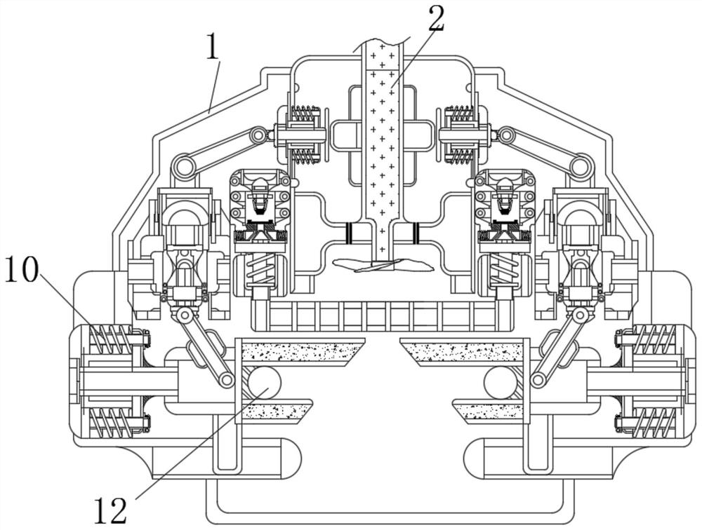
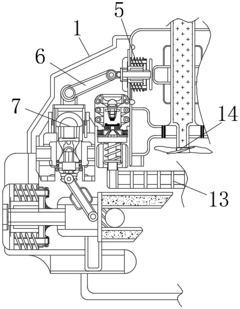
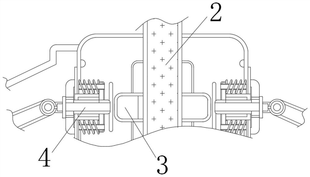
[0024] see Figure 1-5 , a device that automatically protects the suction end of the turbine to ensure normal operation, including a housing 1, a rotating shaft 2 is movably connected inside the housing 1, and a fan 14 is fixedly connected to the lower end of the rotating shaft 2, and the fan 14 is located at the upper end of the protective plate 13. There are small holes inside the plate 13, the left end of the rotating shaft 2 is fixedly connected with a bum...


PUM


Abstract

The invention relates to the technical field of turbines, and discloses a device for automatically protecting an air suction end of a turbine to guarantee normal work. The device comprises a shell, a rotating shaft is movably connected in the shell, a fan is fixedly connected to the lower end of the rotating shaft, and a convex block is fixedly connected to the left end of the rotating shaft; and a stress rod is movably connected to the left end of the convex block, the upper end of the stress rod is fixedly connected with a compression spring, the left end of the stress rod is movably connected with a connecting rod, the left end of the connecting rod is movably connected with a guide column, and the lower end of the guide column is movably connected with a push rod. When a collecting mechanism moves rightwards, particles on the surface of the lower end of a protective plate are removed, meanwhile, when the fan rotates, air in the collecting mechanism is absorbed, and due to the fact that the collecting mechanism moves rightwards, the particles fall into a gathering hole along the slope face of the right end of the collecting mechanism along with flowing of the air so as to be collected, and therefore, the effect of automatically cleaning and collecting the surface of a filter plate at the lower end of the turbine is achieved.

Description

technical field [0001] The invention relates to the technical field of turbines, in particular to a device for automatically protecting the suction end of a turbine to ensure normal operation. Background technique [0002] With the gradual development of society, people's living standards have been significantly improved. It is the fan in the engine of a car or an airplane, which provides power to the turbine when the exhaust gas emitted by the car is discharged, thereby increasing the fuel and oxygen. contact area, thereby increasing the slew rate, while turbines are also used in other smart emerging industries. [0003] However, at present, there are still defects that need to be overcome in the intake of external air by the turbine. When the turbine inhales external air, it often needs to pass through the filter plate to block the particles in the air. However, when the surface of the filter plate is easy to accumulate Particles affect the inhalation of air. At the same ...

Claims


Application Information

Patent Timeline
IPC IPC(8): F04D29/70F04D29/00F02M35/024F02M35/08F02M35/09F02B37/00
CPCF02B37/00F02M35/024F02M35/084F02M35/09F04D29/002F04D29/703Y02T10/12
Inventor 何梓昕
Owner 何梓昕
Learn More