Gas combustor

a combustor and gas technology, applied in the direction of diaphragm valves, combustion types, engine diaphragms, etc., can solve the problems of gas ejecting nozzles not being able to supply normal fuel gas, combustion efficiency not being able to be increased, accidents may occur, etc., and achieve the effect of easy clogging

Active Publication Date: 2013-11-21
TSAI CHIN LIN
View PDF5 Cites 12 Cited by
  • Summary
  • Abstract
  • Description
  • Claims
  • Application Information

AI Technical Summary

Benefits of technology

[0009]One primary objective of the present invention is to provide a gas combustor, in which the upstream end of a pressure stabilizing device is installed with a gas intake valve used for controlling whether fuel being supplied to the pressure stabilizing device, a filter member is further installed for filtering the impurities contained in fuel, thereby solving the problem of a gas ejecting nozzle of a gas discharge device being easily to be clogged.

Problems solved by technology

However, the interior of the gas tank may have metal debris generated by the inner wall being corroded or the electroplating layer being peeled off, so some impurities such as particles may be contained in the gas tank, the impurities often causes the gas ejecting nozzle of a gas discharge device to be clogged thereby causing the gas ejecting nozzle not being able to normally supply the fuel gas.
At this moment, the liquid gas may not be vaporized in time due to the high pressure released, so as to be directly ejected from a flame nozzle in the liquid phase, thereby generating incomplete combustion, thus the combustion efficiency is not able to be increased and accidents may therefore occur.
Furthermore, on some low temperature occasions, because the environmental temperature is relatively low, the liquid gas would not be fully vaporized while the liquid gas in the gas tank being converted into gaseous phase, thereby causing a disadvantage of the gas combustor not being easily to be ignited.
As such, how to effectively filter the impurities contained in fuel for being used in a gas combustor is a serious issue to be concerned by skilled people in the art.

Method used


Image

  • Gas combustor
  • Gas combustor
  • Gas combustor

Examples


Embodiment Construction

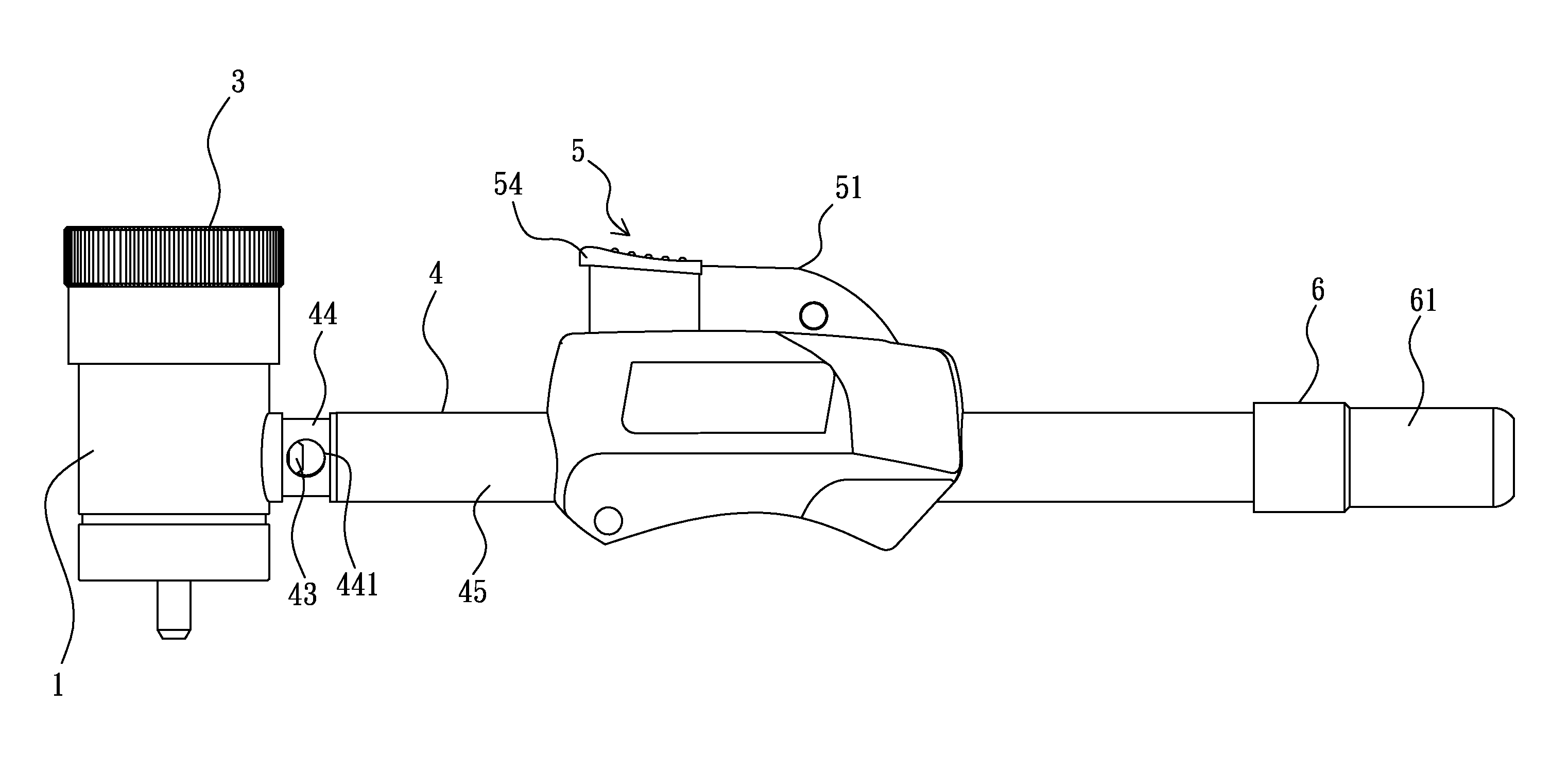
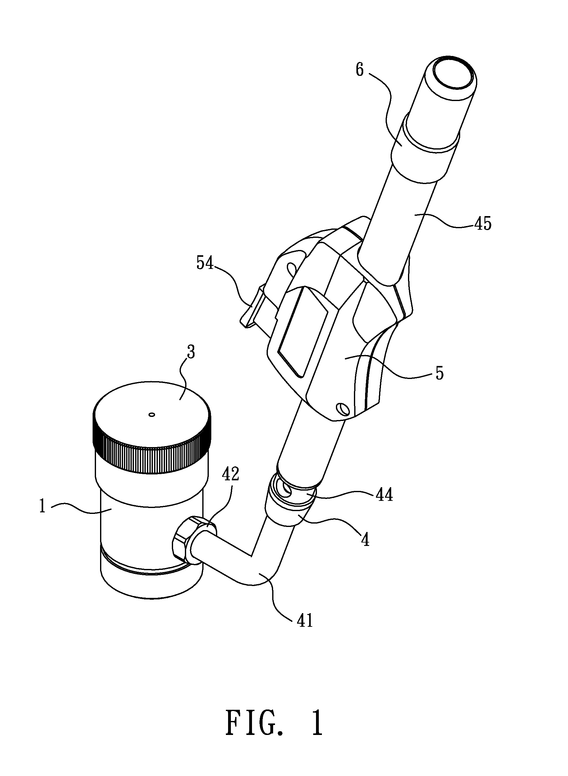
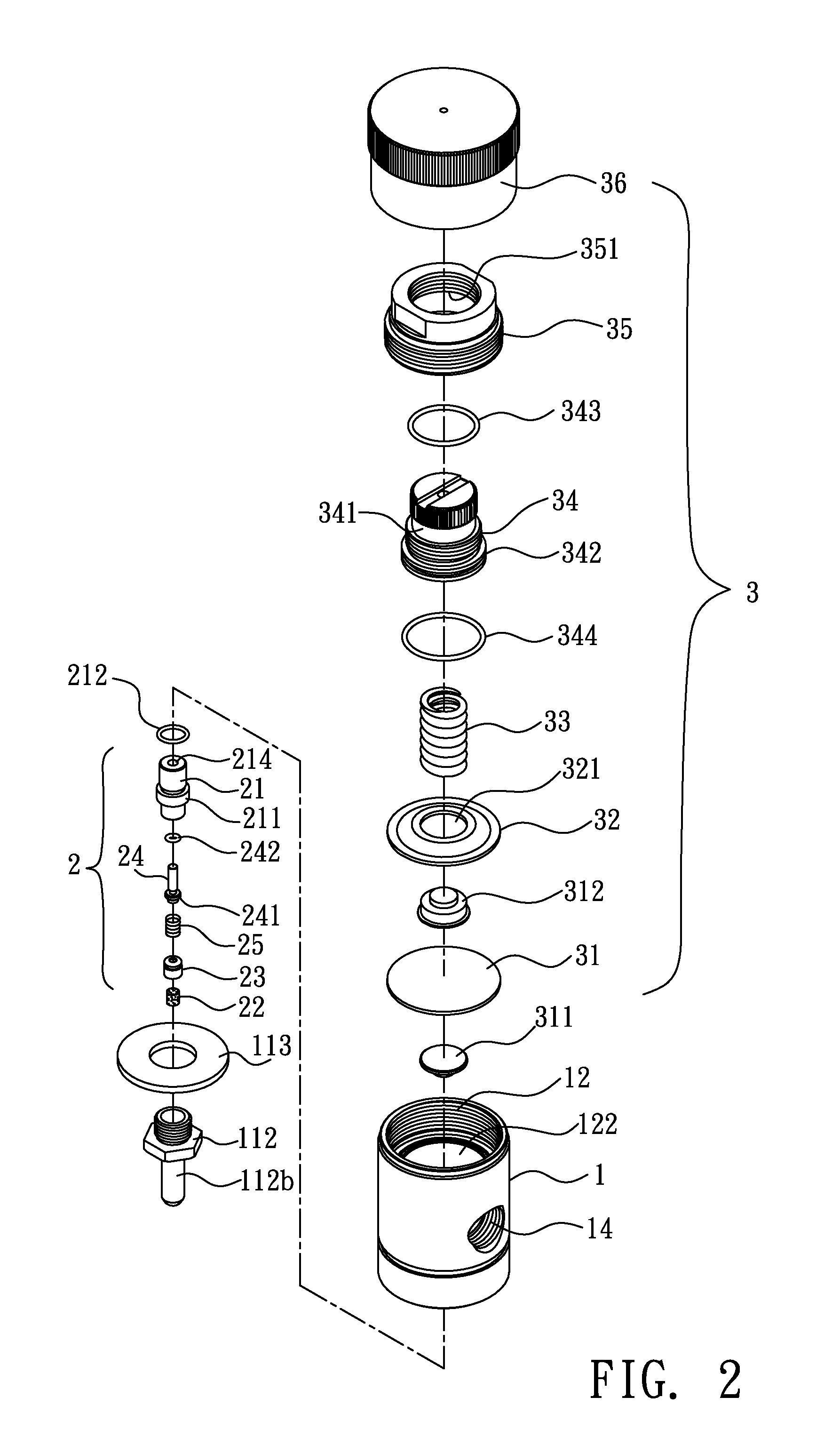
[0021]Referring from FIG. 1 to FIG. 8, wherein FIG. 1 is a perspective view illustrating the gas combustor according to a first embodiment of the present invention; FIG. 2 is a perspective exploded view illustrating the base, the pressure stabilizing device and the gas intake valve according to the first embodiment of the present invention; FIG. 3 is a cross sectional view illustrating the assembly of the base, the pressure stabilizing device and the gas intake valve shown in FIG. 2 according to the first embodiment of the present invention; FIG. 4a is a cross sectional view illustrating the operation of the pressure stabilizing device and the gas intake valve according to the first embodiment of the present invention; FIG. 4b is another cross sectional view illustrating the operation of the pressure stabilizing device and the gas intake valve according to the first embodiment of the present invention; FIG. 5 is a perspective exploded view illustrating the gas discharge device, the ...


PUM


Abstract

The present invention relates to a gas combustor, comprising: a gas intake valve, the bottom of a valve tube axially formed in a valve member is installed with a filter member, a first spring is installed above the filter member and inside the valve tube, the top of a valve pin is protruded out of a tube opening formed at and communicated with the top of the valve tube, a plug outwardly protruded at the bottom of the valve pin is abutted against the first spring, the plug is enabled to seal the tube opening through the first spring being stretched, and when the top of the valve pin is axially subject to a force, the valve pin and the plug are downwardly moved, the first spring is compressed thereby enabling the tube opening to be opened.

Description

BACKGROUND OF THE INVENTION[0001]1. Field of the Invention[0002]The present invention relates to a gas combustor, especially to a gas combustor capable of filtering the impurities contained in fuel.[0003]2. Description of Related Art[0004]Fire is a must have element in our lives, with fire, we can cook food, can be provided with lighting, and the fire can also be used for combustion operations such as forging, soldering and welding. Take a gas tank for example, liquid gas is contained therein, the gas tank can be used for refilling a lighter or combined in a portable gas stove for lighting objects or cooking food, thereby providing convenience in use. In addition, the gas tank has feature of easy to be carried around and stored, so it plays an important role in our lives which cannot be easily replaced.[0005]With the convenience provided by the gas tank, there are two types of gas combustors in the marketplace, take the U.S. Pat. No. 5,466,149 (corresponding to the Taiwan Utility Pa...

Claims


Application Information

Patent Timeline
Patent Type & Authority Applications(United States)
IPC IPC(8): F23D14/28F23D14/02F23Q7/12F16K7/00
CPCF23D14/28F16K7/00F23D14/02F23Q7/12F16K31/1262F23D14/38F23D14/68F23Q3/00Y10T137/8122
Inventor TSAI, CHIN-LIN
Owner TSAI CHIN LIN
Why Eureka
Try Eureka