[0030](A) The cutting bar for dental use according to the present invention has advantages of both a cutting bar having a cutting blade which is formed in a head at the tip and specialized and exclusively used for cutting of soft dentin and
a diamond point specialized and exclusively used for cutting of hard enamel. Therefore, with the cutting bar for dental use according to the present invention, it is possible to cut both dentin and enamel with only a single bar unanesthetically and efficiently without causing any pain or unpleasant sensation to the patient.
[0031](B) In particular, when it is attempted to cut the carious
colored dentin or the soft dentin present in the cavity floor using the conventional cutting bar, the cutting blade formed in the head may inevitably come into contact with the hard enamel present in the
surface layer of the tooth to cause unpleasant sensation to the patient. However, the present invention solves this problem. The diamond
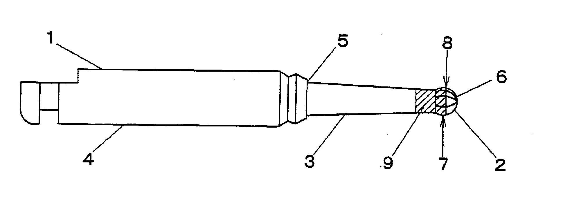
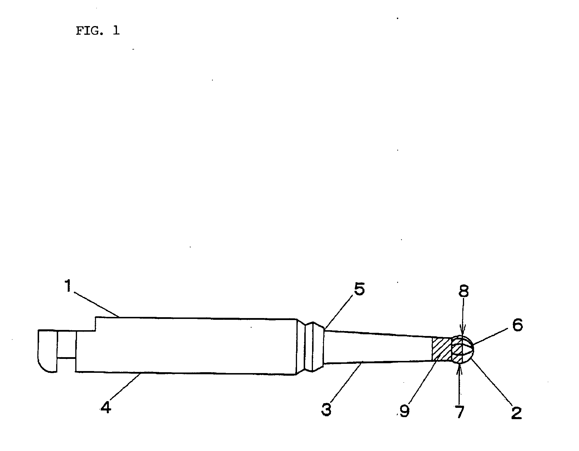
abrasive grains are electrodeposited in a predetermined range extending from the substantially
maximum diameter portion of the head to the neck forming the cutting bar, more specifically, a range of 1 to 2 mm in the neck direction from a region of 0.05 to 0.15 mm in the tip direction from the
maximum diameter portion of the head. Therefore, it is possible to efficiently cut the soft dentin with the cutting blade at the tip not electrodeposited with the diamond
abrasive grains and cut a contact portion with hard enamel, which is inevitably caused according to the cutting of the dentin, with an electrodeposited portion electrodeposited with the diamond abrasive grains.
[0032](C) In the cutting blade at the tip not electrodeposited with the diamond abrasive grains, clogging is less easily caused and efficient dentin removal is possible even if soft dentin is cut. In the electrodeposited portion which is electrodeposited with the diamond abrasive grains, a cutting surface is smooth, and hence little vibration is given to the patient and unpleasant sensation are not caused even if the cutting surface comes into contact with the enamel. Even when it is unnecessary to cut the enamel during cutting of carious dentin, the diamond abrasive grains are electrodeposited on the cutting blade surface excluding the tip. Therefore, even if the cutting blade comes into contact with the hard enamel, unpleasant sensation, in particular, vibration is not given to the patient.
[0033](D) Therefore, though efficient dental treatment cannot always be performed by the conventional cutting bar for dental use specialized and exclusively used for dentin to be cut because a cutting bar and a handpiece need to be replaced every time according to the tooth structure to be cut, with the cutting bar for dental use according to the present invention, it is possible to cut both dentin and enamel with only a single bar unanesthetically and efficiently without causing any pain or unpleasant sensation to the patient. In particular, it is possible to fundamentally solve the problem in that the cutting blade of the cutting bar rotating at low speed comes into contact with the hard enamel present in the surface layer of the tooth during cutting of carious dentin to cause unpleasant sensation to the patient.
[0034](E) With the cutting bar according to the present invention having the spherical or semispherical head, the diamond abrasive grains are electrodeposited in the round portion extending to a boundary between the head and the neck from the region of 0.05 to 0.15 mm in the tip direction from the maximum
diameter portion of the head. Therefore, it is possible to extremely easily impart a round bevel to an enamel cavity margin in composite resin restoration. This also contributes to efficiency of dental treatment.
[0035](F) Whereas the head in which the cutting blade is formed is a region for cutting not only soft dentin but also hard enamel, with the cutting bar according to the present invention, the head of which is made of
hard metal containing
tungsten carbide as a main component, it is possible to sufficiently expect improvement of a cutting performance and extension of the life of the cutting bar. The same holds true for the cutting bar for dental use, the neck of which is made of
hard metal containing
tungsten carbide as a main component.

