Two-cycle combustion engine with air scavenging system having pressure reducing device

a two-cycle combustion engine and air scavenging technology, which is applied in the direction of combustion engines, combustion air/fuel air treatment, combustion feed systems, etc., can solve the problems of lowering the cooling performance of a fuel component, the concentration of air-fuel mixture within the engine cylinder tends to be lowered, and the combustion chamber is not sufficiently cooled. to achieve the effect of enhancing the pressure reducing

Active Publication Date: 2006-01-12
KAWASAKI MOTORS LTD
View PDF22 Cites 13 Cited by
  • Summary
  • Abstract
  • Description
  • Claims
  • Application Information

AI Technical Summary

Benefits of technology

[0007] Accordingly, the present invention is intended to provide an improved air scavenging type two-cycle combustion engine equipped with a pressure reducing device, which is effective to suppress the blow-off of the air-fuel mixture through the exhaust port and in which clogging of a decompressing hole can easily be removed, even though such clogging occurs, to thereby enhance the pressure reducing effect

Problems solved by technology

It has, however, been found that in the two-cycle combustion engine with the air scavenging system such as disclosed in the first mentioned Japanese publication, although both the amount of unburned gases being blown off and the fuel consumption are rendered small, the concentration of the air-fuel mixture within the engine cylinder tends to be lowered as a result of the scavenging with air, accompanied by lowering of the cooling performance exhibited by a fuel component and, therefore, the combustion chamber will not be sufficiently cooled when, for example, the combustion engine is abruptly decelerated from a fully loaded operating condition down to the idling speed.
Due to such insufficient cooling of the combustion chamber, even after the ignition switch has been turned off to halt the engine, the temperature of the air-fuel mixture in the combustion chamber at the time of the start of compression remains high, resulting in the “run-on (or self ignition)” phenomenon, in which the combustion engine continues to fire.
However, it has been found that in this decompressing groove, a quantity of fuel deposited in the vicinity of an exit end thereof may be charred to form a carbon deposit, which constitutes a cause of clogging occurring in the vicinity of the exit end of the decompressing groove to such an extent as to result in closure of the decompressing groove.
Also, since the position at which the decompressing groove can be formed is limited to a site around the scavenging port, complicated and time-consuming procedures would be required to clean off the deposit clogging in the vicinity of the exit end of the decompressing groove.

Method used


Image

  • Two-cycle combustion engine with air scavenging system having pressure reducing device
  • Two-cycle combustion engine with air scavenging system having pressure reducing device
  • Two-cycle combustion engine with air scavenging system having pressure reducing device

Examples


Embodiment Construction

[0034] Hereinafter, preferred embodiments of the present invention will be described in detail with reference to the accompanying drawings.

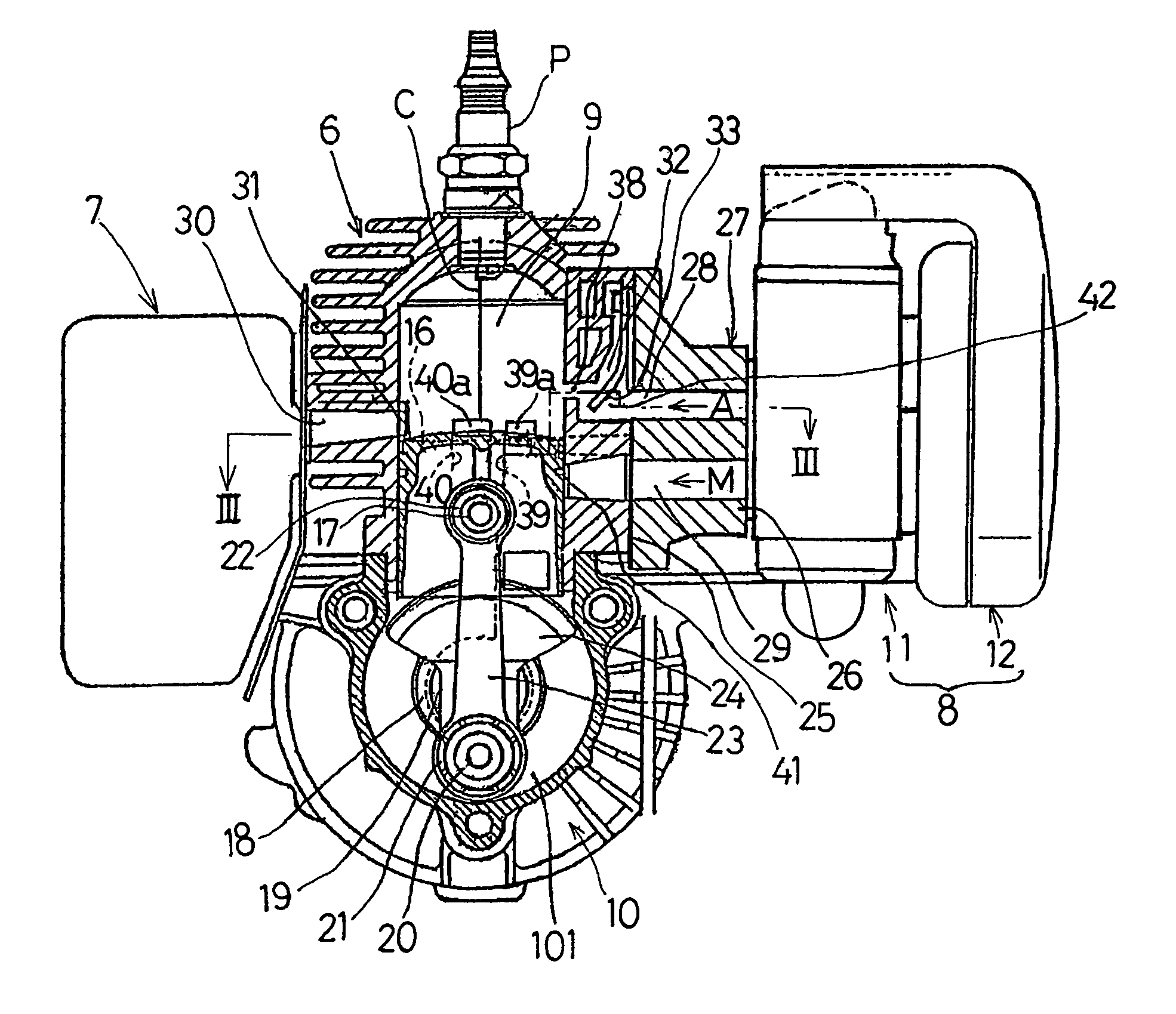
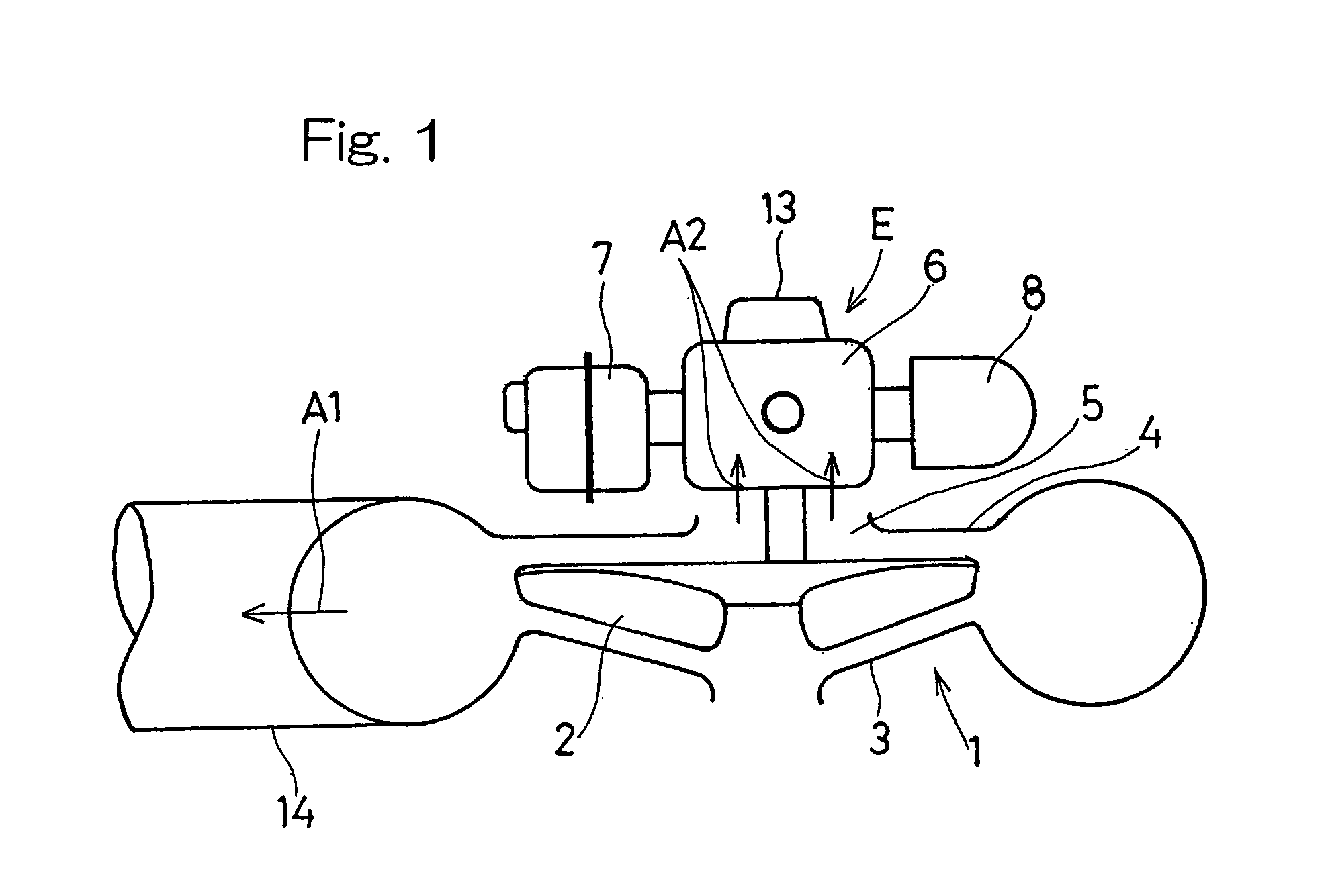
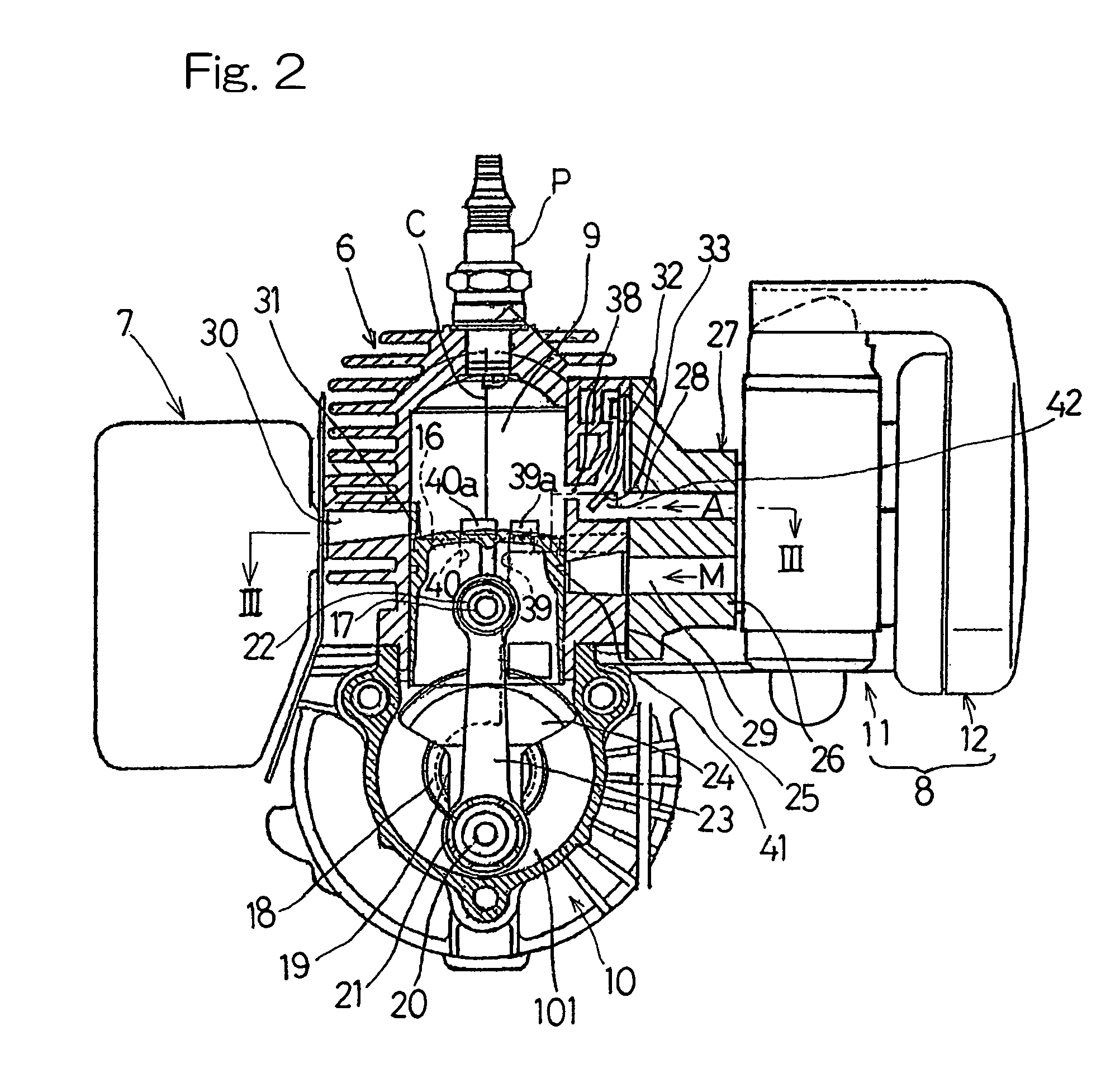
[0035] Referring to FIG. 1, there is shown a schematic plan view of a small-size blowing machine utilizing an air scavenging type combustion engine equipped with a pressure reducing device according to a first preferred embodiment of the present invention. The blowing machine 1 shown in FIG. 1 includes a blower fan 2 and a fan casing 3, and a combustion engine E for driving the fan 2 is coupled with and positioned rearwardly of the fan casing 3. The combustion engine E includes a recoil starter 13 mounted on a rear face thereof and an engine cylinder block 6 positioned at a location confronting an air delivery port 5 defined in a rear wall 4 of the fan casing 3. An exhaust silencer 7 is connected with a side portion (a left side portion, as viewed in FIG. 1) of the cylinder block 6, and an air intake device 8 including a carburetor or a fuel sup...


PUM


Abstract

To provide an improved air scavenging type two-cycle combustion engine equipped with a pressure reducing device in which clogging of a decompressing hole can easily be removed, a two-cycle combustion engine includes a delivery passage (32) for introducing air into a combustion chamber (9) prior to an air-fuel mixture. This delivery passage (32) has a downstream opening (32c) through which the air is introduced into the combustion chamber by way of a scavenging port (40a). A decompressing hole (38) is defined for communicating the combustion chamber (9) to a portion of the delivery passage (32) and is closed by a piston (16) then ascending, at a timing delayed relative to closure of an exhaust port (31).

Description

BACKGROUND OF THE INVENTION [0001] 1. Field of the Invention [0002] The present invention generally relates to a two-cycle combustion engine having an air scavenging system, which can be utilized as a drive source for a small-size work machine such as, for example, a brush cutter or a blast cleaner. More particularly, the present invention relates to the two-cycle combustion engine of the type referred to above, having a pressure reducing device for discharging compressed gases within an engine cylinder. [0003] 2. Description of the Prior Art [0004] The two-cycle combustion engine having an air scavenging system is well known in the art. Specifically, the conventional two-cycle combustion engine with the air scavenging system is generally so designed that prior to a combustion chamber being scavenged with an air-fuel mixture, the combustion chamber is initially scavenged with an air to suppress a blow-off of the air-fuel mixture through an exhaust port. In this conventional two-cycl...

Claims


Application Information

Patent Timeline
Patent Type & Authority Applications(United States)
IPC IPC(8): F02B25/00
CPCF02B25/22F02M35/1019F02M35/1017
Inventor YUASA, TSUNEYOSHIKOBAYASHI, MASANORI
Owner KAWASAKI MOTORS LTD
Why Eureka
Try Eureka