Construction machine

Active Publication Date: 2014-05-08
HITACHI CONSTR MASCH CO LTD
View PDF3 Cites 12 Cited by
  • Summary
  • Abstract
  • Description
  • Claims
  • Application Information

AI Technical Summary

Benefits of technology

[0014]With this arrangement, the indoor air filter provided in the duct accommodating space can be arranged at a position higher than the footrest area. Therefore, fine sands, dusts and the like remaining and floating over the footrest area cannot easily adhere to the indoor air filter, and clogging of the indoor air filter due to the sands, dusts and the like remaining on the footrest area can be prevented.
[0015]As a result, since clogging of the indoor air filter can be prevented, the frequency of the maintenance work such as inspection, cleaning a

Problems solved by technology

As a result, the indoor air filter can be easily clogged, and a frequency of a maintenance work of the indoor air filter such as inspection, cleaning and the like increases, which causes a problem that workability is poor.
Particularly, since th

Method used


Image

  • Construction machine
  • Construction machine
  • Construction machine

Examples


first embodiment

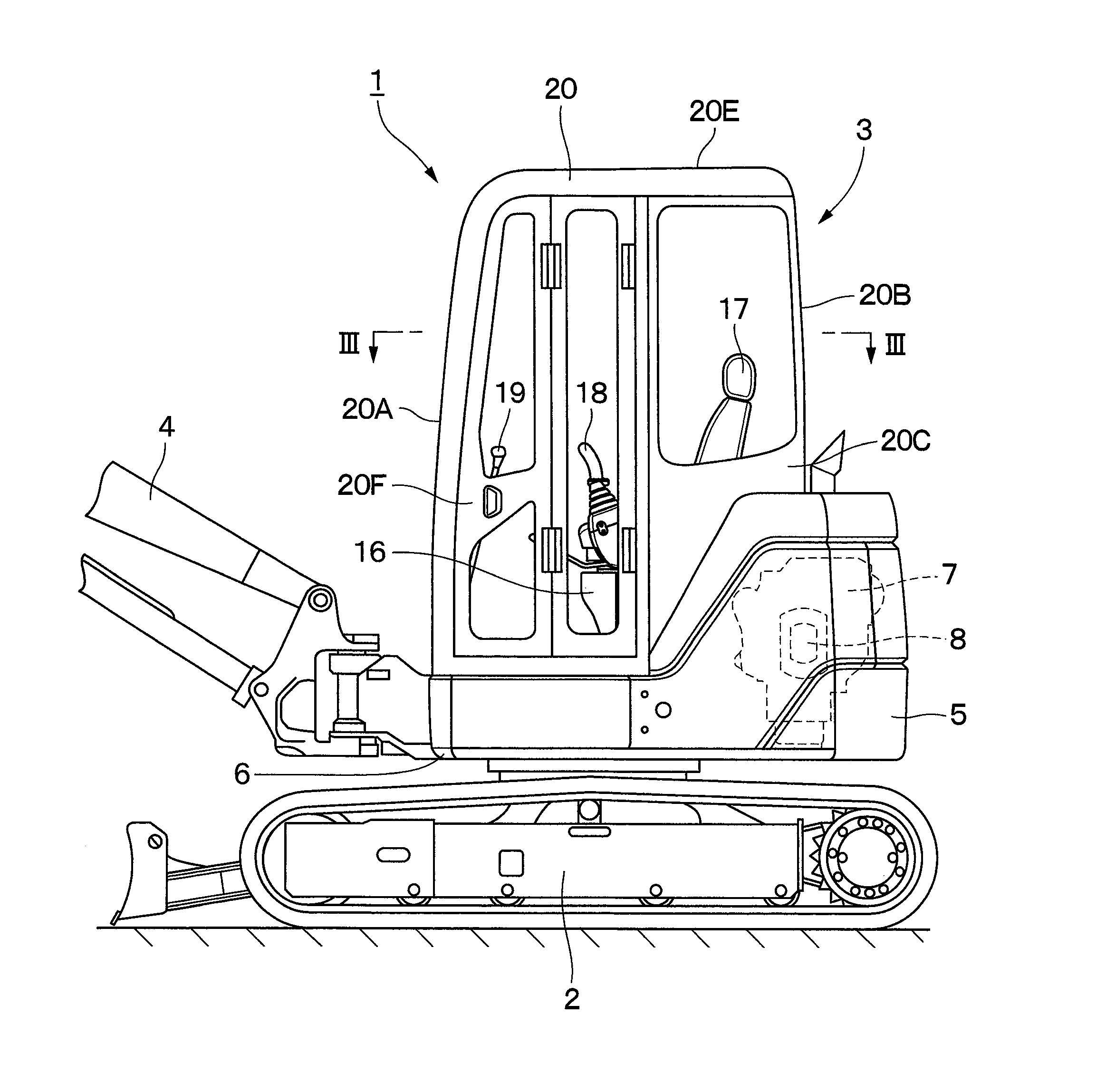
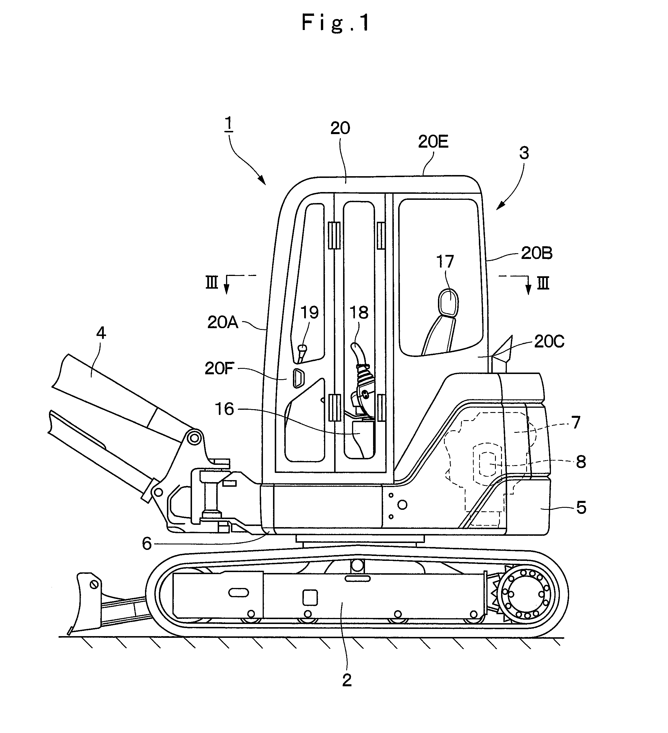
[0048]FIGS. 1 to 15 illustrate the construction machine according to the present invention.

[0049]In FIG. 1, designated at 1 is a crawler type hydraulic excavator as a construction machine applied to the first embodiment. This hydraulic excavator 1 is a small-sized hydraulic excavator called mini excavator suitable for a work in a narrow working site. The hydraulic excavator 1 is composed of an automotive lower traveling structure 2, an upper revolving structure 3 rotatably mounted on the lower traveling structure 2, a working mechanism 4 provided on the front side of the upper revolving structure 3 and carrying out an excavating work of earth and sand and the like, and a counterweight 5 provided on the rear side of the upper revolving structure 3. This counterweight 5 is to take a balance with the working mechanism 4 and is formed by being curved in an arc shape so as to cover the rear side of an engine 7 which will be described later.

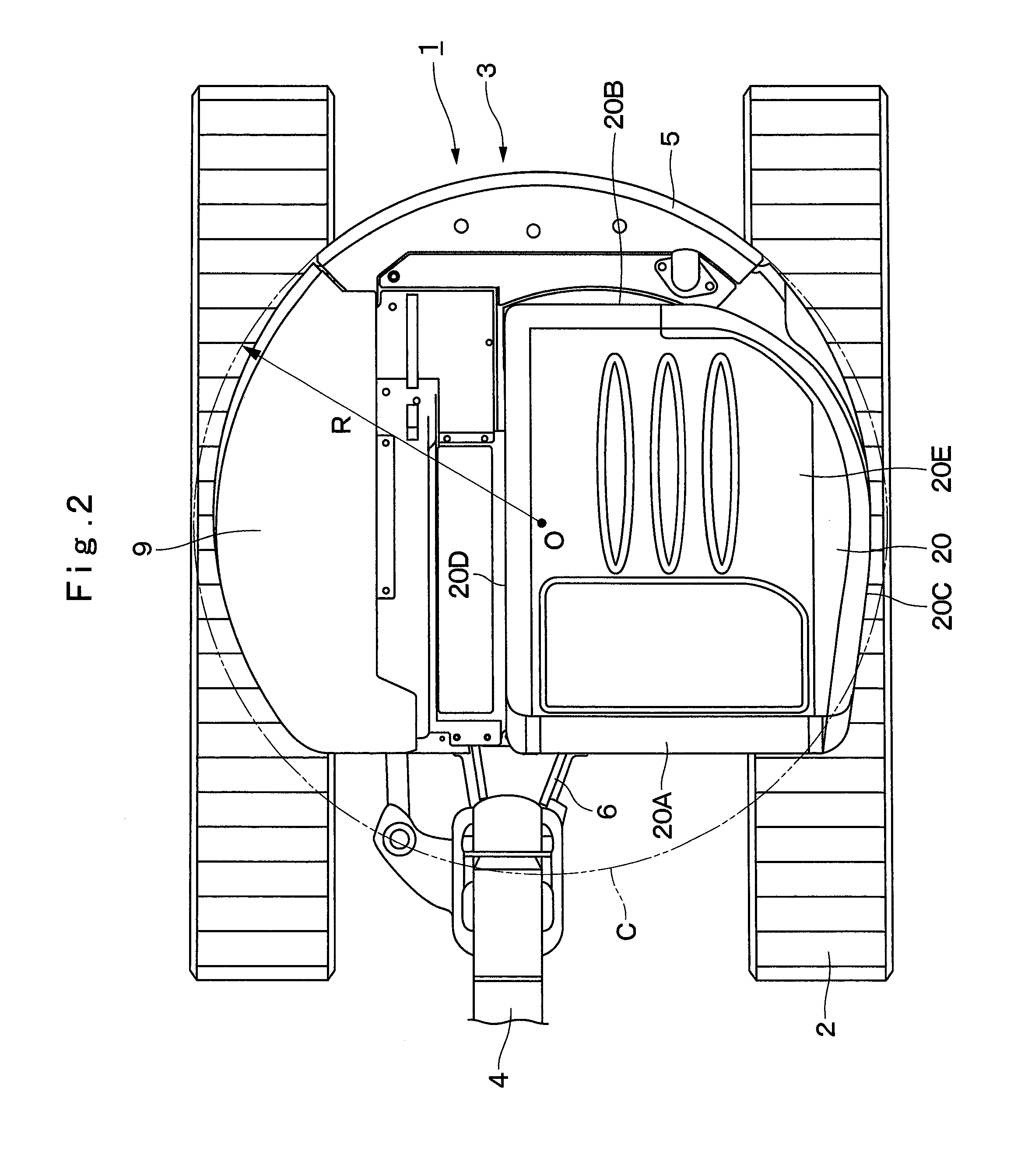
[0050]As shown in FIG. 2, the upper revolving st...

second embodiment

[0102]Subsequently, a configuration of the indoor air inlet duct 38 which is the feature portion will be described by referring to FIGS. 18 to 22.

[0103]Designated at 38 is the indoor air inlet duct according to the second embodiment provided in the duct accommodating space 35 of the seat base 32. As shown in FIGS. 18, 22 and the like, this indoor air inlet duct 38 is composed of a box body 39 and a filter fitting hole 40 substantially similarly to the indoor air inlet duct 23 according to the first embodiment. However, the indoor air inlet duct 38 according to the second embodiment is different from the indoor air inlet duct 23 according to the first embodiment in a point in which the indoor air inlet duct 38 is configured to be connected to the indoor air inlet duct connecting portion 22B1 of the indoor unit 22 through a reinforcing connecting pipe 44.

[0104]Here, the box body 39 is provided in the vertically laid state extending in a perpendicular direciotn in the duct accommodati...


PUM


Abstract

On a seat base (11) of a floor member (10), a rear surface plate (11C), an operator's seat mounting plate (11D) on which an operator's seat (17) is mounted at a position higher than a footrest area (12) on which the foot is placed, and a duct accommodating space (14) formed in the vertical direction among the rear surface plate (11C), the operator's seat mounting plate (11D), and a rear position (12B) of the footrest area (12) are provided. An indoor air inlet duct (23) having the front surface side opened as a filter fitting hole (25) and introducing air in an occupying space (21) toward an indoor unit (22) of an air-conditioning unit is provided on the duct accommodating space (14). An indoor air filter (26) for catching dusts in the air is provided on the filter fitting hole (25) of the indoor air inlet duct (23).

Description

TECHNICAL FIELD[0001]The present invention relates to a construction machine provided with a cab box on a floor member, for example, or to a construction machine such as a hydraulic excavator, a hydraulic crane and the like, for example.BACKGROUND ART[0002]In general, a hydraulic excavator which is a typical example of a construction machine is composed of an automotive lower traveling structure, an upper revolving structure rotatably mounted on the lower traveling structure, and a working mechanism provided capable of moving upward / downward on the front side of the upper revolving structure.[0003]The upper revolving structure is composed of a revolving frame forming a support structural body, a floor member provided on the revolving frame, in which the rear side is a seat base on which an operator's seat is mounted and the front side is a footrest area on which the operator places the foot, a cab box provided by covering the periphery and the upper part of the floor member in order...

Claims


Application Information

Patent Timeline
IPC IPC(8): B62D33/06B60H1/00
CPCB60H1/00378B62D33/0617B60H2003/065B62D25/20B62D33/06E02F3/325E02F9/0858E02F9/16B60H1/00B60H3/06B66C13/52
Inventor KIMURA, SHOGOTANAKA, TOMOYUKITABETA, HIROSHI
Owner HITACHI CONSTR MASCH CO LTD
Why Eureka
Try Eureka