Supercharge Your Innovation With Domain-Expert AI Agents!

Natural gas diffusion amount monitoring device and method in gas pipeline construction process

A gas pipeline and monitoring device technology, which is applied in the pipeline system, gas/liquid distribution and storage, instruments, etc., can solve the problems of error, frictional resistance of the pipeline to be replaced, and the inability to obtain the actual pressure of the pipeline, etc., to achieve instantaneous component accuracy Effect

Active Publication Date: 2021-08-13
TONGJI UNIV
View PDF6 Cites 0 Cited by
  • Summary
  • Abstract
  • Description
  • Claims
  • Application Information

AI Technical Summary

Problems solved by technology

Theoretically, according to the actual physical parameters of the pipeline and the pressure of the upstream pipeline, the dynamic composition and velocity at the release pipe can be obtained through fluid simulation, and the proportion of natural gas in the total release can be directly determined. However, because the pressure of the upstream pipeline varies with The use of the pipes connected to it will change, and the frictional resistance of the pipes to be replaced will also have an impact. Simple simulation calculations cannot give credible results.
[0006] In the current construction process, only rely on the empirical method of methane concentration measurement to ensure that there is no large amount of air in the pipeline to be replaced, and do not measure the amount of natural gas released during the construction process. If the flow meter is used to measure directly, the mixed gas flow rate is obtained instead of The proportion of natural gas cannot be distinguished, and the actual pressure upstream of the pipeline cannot be obtained by relying solely on fluid simulation calculations, which will cause large errors

Method used


Image

  • Natural gas diffusion amount monitoring device and method in gas pipeline construction process
  • Natural gas diffusion amount monitoring device and method in gas pipeline construction process
  • Natural gas diffusion amount monitoring device and method in gas pipeline construction process

Examples


Embodiment

[0044] The invention combines fluid simulation technology with on-site actual measurement, not only can clearly give pipeline pressure through actual measurement, but also can verify data such as flow velocity and dynamic pressure obtained by simulation according to actual measurement results. It has the advantages of easy operation and remote recording, and can accurately show the amount of natural gas released during each replacement process.

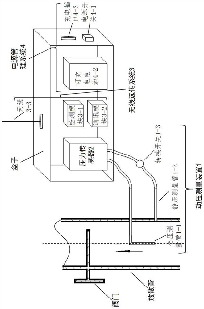
[0045] Such as figure 1 As shown, the present invention provides a gas pipeline construction process natural gas emission monitoring device, which consists of four parts, including a dynamic pressure measurement component 1, a pressure sensor 2, a wireless remote transmission component 3 and a power management component 4.

[0046] The dynamic pressure measurement assembly 1 includes a total pressure measurement tube 1-1, a static pressure measurement tube 1-2 and a transfer switch 1-3.

[0047] The pressure sensor 2 includes a pres...


PUM


Abstract

The invention relates to a natural gas diffusion amount monitoring device and method in a gas pipeline construction process. The device comprises a dynamic pressure measurement assembly which is connected to a diffusion pipe of a to-be-replaced pipeline, and is used for measuring a speed dynamic pressure in the diffusion pipe and a total pressure in a pipeline on site through a pressure sensor connected to the dynamic pressure measurement assembly in the natural gas diffusion process; a wireless remote transmission assembly which is connected to the pressure sensor and used for sending pressure data to a data acquisition instrument; a power management assembly which is used for energizing the pressure sensor and the wireless remote transmission assembly; and the data acquisition instrument and a simulation machine which are used for receiving the pressure data acquired on site and constructing a simulation model for simulation to obtain a total natural gas diffusion amount in a diffusion period. Compared with the prior art, the method has the advantages that on-site actual measurement and fluid simulation technologies are combined, and the method is convenient, accurate, comprehensive in consideration and the like.

Description

technical field [0001] The invention relates to the field of gas pipeline construction monitoring, in particular to a device and method for monitoring natural gas emission during gas pipeline construction in combination with fluid simulation and on-site measurement. Background technique [0002] Before the construction of the natural gas pipeline is completed and the natural gas is about to be connected, a replacement (or "drainage") process must be carried out to release the residual air or natural gas-air mixture in the pipeline into the atmosphere to prevent the natural gas used by users from containing air. Once the natural gas-air mixture enters the user's combustion equipment, it will cause serious accidents such as explosions. [0003] The current operation process after construction is completed, such as image 3 shown. Install a release pipe on the downstream side, usually a short pipe of DN50, and slowly open the upstream valve V1, for gate valves, generally 1 / 4 o...

Claims


Application Information

Patent Timeline
IPC IPC(8): F17D1/02F17D3/01F17D3/10G06F30/17G06F30/28G06F113/08G06F113/14G06F119/14
CPCF17D1/02F17D3/01F17D3/10G06F30/17G06F30/28G06F2119/14G06F2113/08G06F2113/14
Inventor 秦朝葵谢依桐陈志光
Owner TONGJI UNIV
Features
  • R&D
  • Intellectual Property
  • Life Sciences
  • Materials
  • Tech Scout
  • Unparalleled Data Quality
  • Higher Quality Content
  • 60% Fewer Hallucinations
Learn More