Remote lampblack integrated purification intelligent control system based on Internet of Things and method of remote lampblack integrated purification intelligent control system
An intelligent control system and Internet of Things technology, applied in chemical instruments and methods, transmission systems, and oil fume removal, etc., can solve problems such as loss of use function, scattered distribution, and uneffective control of kitchen oil fume emissions, and achieve the effect of saving electric energy
- Summary
- Abstract
- Description
- Claims
- Application Information
AI Technical Summary
Problems solved by technology
Method used
Image
Examples
Embodiment 1
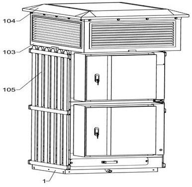
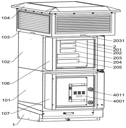
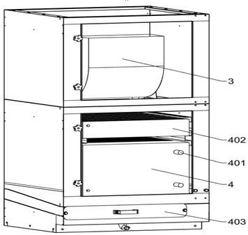
[0048] Remote fume integrated purification intelligent control system and method based on Internet of Things, such as Figure 1-Figure 3 and Figure 16 As shown, it includes a data server, an intelligent communication gateway, a connection base 1, a purification box 101, an exhaust box 102, an air outlet box 103, a rain cover 104, a protective plate 105, a control box 106, a first hinge 1061, and an electric heat dissipation Fan 1062, connection box 107, second hinge 1071, on-site terminal server 2, exhaust system, flue gas purification unit 202, noise detection system, flue gas information collection system, working condition monitoring unit 205, exhaust mechanism and flue gas Purification mechanism, the lower end of the connection base 1 is fixedly installed above the building flue opening and is in sealing communication with it, the lower end of the purification box 101 is installed on the upper end of the connection base 1 through bolts and communicated with it, and the lo...
Embodiment 2
[0051] On the basis of Example 1, such as figure 2 and Figure 16 As shown, the data server includes a data control unit, a data storage unit and a data alarm unit. The data server establishes a data connection with the on-site terminal server 2 through an intelligent communication gateway. The data control unit, the data storage unit and the data alarm unit are connected to the data server electrical Connection, the data server is used for data integration of the data control unit, data storage unit and data alarm unit, the real-time data of the device operation can be watched at any time through the display, and the data control unit is used for the adjustment of the working data of the exhaust mechanism and the smoke purification mechanism The control and data storage unit are used for real-time data storage and monitoring of the device, and the data alarm unit is used for alarming when the data parameters of the device exceed the range.
[0052] When in use, the staff co...
Embodiment 3
[0054] On the basis of Example 2, such as figure 2 , Figure 4 and Figure 16 As shown, the exhaust system includes an exhaust unit 201 and a pressure sensor 2011. The exhaust unit 201 is fixedly connected to the front side of the on-site terminal server 2 and electrically connected to the on-site terminal server 2. The pressure sensor 2011 is fixedly connected to the connection base 1 The lower inner wall, the pressure sensor 2011 is electrically connected to the exhaust unit 201, and the pressure sensor 2011 is used to detect the air pressure in the flue.
[0055] When the resident turns on the range hood, the air pressure in the flue will change according to the number of range hoods turned on by the resident. The more the range hood is turned on, the greater the air pressure in the flue. In order to detect the real-time change of the air pressure in the flue, the collected information is transmitted to the exhaust unit 201 in real time, and then the exhaust unit 201 tra...
PUM
 Abstract
Description
Claims
Application Information
 - R&D Engineer
- R&D Manager
- IP Professional
- Industry Leading Data Capabilities
- Powerful AI technology
- Patent DNA Extraction
Browse by: Latest US Patents, China's latest patents, Technical Efficacy Thesaurus, Application Domain, Technology Topic, Popular Technical Reports.
© 2024 PatSnap. All rights reserved.Legal|Privacy policy|Modern Slavery Act Transparency Statement|Sitemap|About US| Contact US: help@patsnap.com


