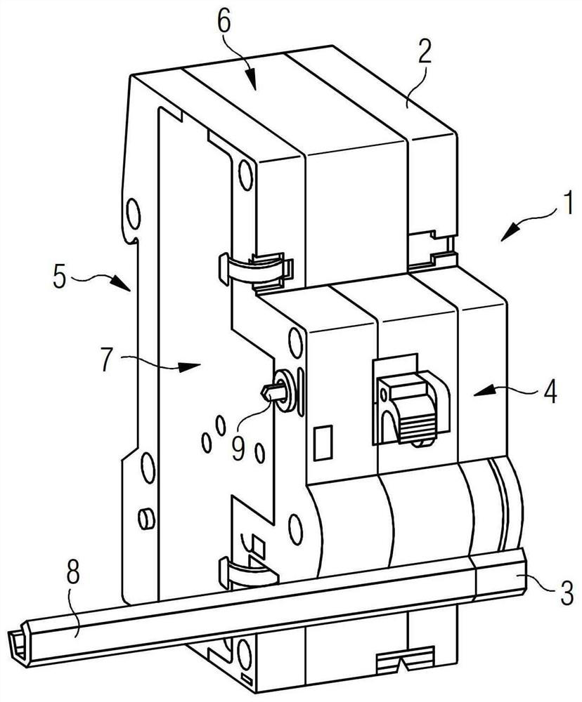
[0044] figure 1 A schematic diagram of a remote drive 1 having an automatic re-switching function (ARD: Automatic Reclosing device) is shown in a stereoscopic figure. The remote drive 1 has an insulating material housing 2 having a front side 4, a fixed side 5 opposite the front side 4 and a narrow side 6 and a wide side 7 having a connection front side 4 and a fixed side 5. An operational element 3 is disposed on the front side 4, which can be protected by the engagement connector 8 (GriffVerbinder) and the fault current protection switch device 100 (see figure 2 The operating element is coupled to it can be operated by means of remote drive 1 in a coupled state, i.e., turning on, and disconnecting. Remote driver 1 can be secured to the support rail or mounting rail (not shown) by its fixed side 5, and the support rail or mounting rail is mainly used in the electrical mounting dispenser for the device to be fixed.
[0045] On the wide side 7 of the fault current protection switch device 100 to be coupling, the remote driver 1 further has an input interface 9 for receiving a trigger signal of the coupled fault current protection switching device 100. exist figure 1 In the view, the input interface 9 is mechanically designed; however, it may be also possible, and the trigger signal is transmitted from the fault current protection switch device 100 to the remote driver 1. The mechanical trigger signal can be achieved, for example, by integrating the auxiliary switch in the fault current protection switch device 1 to be coupled.
[0046] exist figure 2 A conceptual structure of the remote driver 1 according to the present invention is shown in a side view. Remote Drive 1 has a drive device 20 for remote operation of operating element 3. To this end, the operating element 3 is protruded on the engaging roller 11 to rotate around its rotation shaft 12 when the operation element 3 is operated. In the illustrated example, the drive device 20 has a transmission device having a gear 21 in addition to a motor (not shown), the gear 21 meshes with a teeth 13 that is designed to the ring circumference of the engagement roller 11. With the motor-transmission-unit, the rotational speed of the motor can match the torque required to operate with the protection switch device 100 coupled to the remote drive 1, and thus is coupled to the operating element 3 by the engagement connector 8. Mechanical load matches. However, for the sake of clarity, image 3 Motivation and transmission are not shown or not fully shown. Further, the drive device 20 can also be designed to be non-transmission: In this case, the motor is controllable and directly, that is, without the transmission of the transmission of one or more gear levels. The teeth 13 on the engrave roller 11 are on.
[0047] In order to control the drive device 20, the remote driver 1 has a control device 30 arranged and designed on the circuit board 10, figure 2 In the illustrated embodiment, the control device includes at least one processor or microcontroller 31 and a storage device 32. Although the various components of the arrangement of the control device are advantageous for the use of a common circuit board due to the modular construction of the various components of the control device and the relatively low assembly of this associated circuit board, it is not critical to the present invention. It may also be possible to connect the respective electronic components to each other without using a common circuit board.
[0048] Further, the control device 30 has two output connections 33 and 34, and in the illustrated example, the two output joints are disposed on one of the narrow side 6 of the housing 2, and can be protected by insertion of electrical connection lines and fault currents. Switching device 100 conductive connection (see image 3 ). In order to perform the Fi test caused by the remote drive 1, the fault current is generated in the fault current protection switch device 100 in the fault current protection switch device 100 to trigger the fault current protection switch device for testing.
[0049] The control device 30 also has a communication device 50 that is also disposed on the circuit board 10 and communicates with the upper unit, such as a control center or control chamber by means of the communication device, or can also be coupled or coupling. Connect the communication of the protection switching device. Communication device 50 is advantageously widely designed. As the transmission standard, for example, ZigBee, Bluetooth or infrared rays can be considered; however, this is not critical to the present invention. The wireless interface can be arranged directly on the circuit board 10; in turn, for wired interface, a suitable connection feasibility is set in the region of the housing surface.
[0050] Further, a measuring device 40 is disposed on the circuit board 10, the measuring device for measuring the potential of the electrical connection line connected to the protection switch device 100 on the remote driver 1. To this end, the measuring device 40 has a plurality of measurement lines 41 that are drawn from the housing 2 of the remote driver 1 and can conduct electrically conductive connections to the corresponding contact position on the fault current protection switch device 100. However, the mode of electrical connection of the measuring device 40 and the contact position is not critical to the present invention. It is therefore equally possible, and in the region of the housing surface of the remote driver 1, the electrical connection can be inserted in which the electrical connection line is electrically connected to the connection line of the fault current protection switch device 100.
[0051] exist image 3 and Figure 4 The remote driver 1 according to the present invention and the first embodiment of the apparatus according to the present invention are shown. Here, image 3 The front view of the apparatus is shown schematically, which is composed of a remote drive 1 and a fault current protection switch device 100 coupled thereto. The fault current protection switch device 100 is designed to be quadrupole, i.e., it is connected to four electrical connection lines (three phase conduits L1, L2, L3, and neutral conductor N). A first end of two test lines T1 and T2 is connected at both electrical connections 33 and 34 on the output side of the control device 30. Two test lines T1 and T2 are part of the test circuit for performing the FIM test of the fixed fault current protection switch device 100. To this end, the second end of the two test lines T1 and T2 is electrically connected to the fault current protection switching device 100 via the connection line L3 and N and the fault current protection switching device 100. It is equally possible, two test lines T1 and T2 are connected to two of the four connecting lines, i.e., three phase conductors L1, L2, and L3, or with three phase conductor L1, One phase conductor in L2, L3 and the neutral conductor N are connected. By applying a test voltage to the two connections 33 and 34, the test current flows through two test lines T1, T2 flows between the connection lines L3 and N, the test current is interpreted as a fault current, by the fault current. This trigger the fault current protection switch device 100.
[0052] Figure 4 Schematic image 3Part of the remote drive 1 shown in the remote drive 1. The control command for starting the Fi test can be transmitted to the control device 30 by the control interface 35. In the example shown, the control interface 35 is wired. It is also possible, however, that the control interface 35 is wirelessly designed and the control command for starting the Fi test is wirelessly transmitted to the control device 30. Through the control command, the test circuit is turned on by the closed switch S1 to perform the Fi test. Test resistor R1 is also arranged in the test circuit, which defines the size of the test current in the main circuit of the fault current to feed the fault current to the main circuit of the fault current protection switch device 100. Here, the test resistor R1 can be implemented as a fixedly set resistor, or implemented as a resistance that can be variable or implemented as a configurable resistor network. In the latter two cases, different fault current protection switching devices 100 can be checked by one of the same remote driver 1, and the fault current protection switch device can be characterized by different rated fault currents.
[0053] The mechanical or electric trigger signal of the fault current protection switch device 100 can be transmitted to the control device 30 of the remote driver 1 by the input interface 9 of the remote driver 1. By means of the microcontroller 31, it can be checked whether the trigger signal is related to the FIM previously started by the control device 30. By communication interface 36 as part of communication device 50 (see figure 2 ), For example, the test result and / or test record can be transmitted to the superior unit. Here, the communication interface 36 can be designed wirelessly or wired, but image 3 and Figure 4 In the view, the communication interface 36 is wired. Further, the test results can be provided additionally to the field signal sensor with the signal contacts to be able to identify the relevant circuits faster in the field. Further, the drive device 20 can also be controlled via the communication interface 36 to re-open the fault current protection switch device 100 coupled to the remote driver 1.
[0054] exist Figure 5 and Image 6 A second embodiment of the device according to the present invention and the apparatus according to the present invention is shown schematically shown. Figure 5 A front view of an alternative device is shown. Image 6 The corresponding portion of the control device 30 is shown again is schematically shown. For the sake of clarity, the test circuit described in detail in the first embodiment is omitted in the view of the second embodiment. However, this does not mean that the embodiment cannot be combined with it: image 3 and Figure 4 The test circuit shown in the first embodiment shown may also be an integral part of the second embodiment.
[0055] The fault current protection switch device 100 is again designed as a quadular and connected to the four electrical connection lines, i.e., three phase conductors L1, L2, L3, and neutral conductor N. The four measurement lines 41 are drawn from the remote driver 1 coupled to the fault current protection switching device 100 and is electrically connected to one of the connecting conductors L1, L2, L3, and N, respectively. Here, the measurement line 41 can be directly connected to the connection lines respectively belonging to their connection, or may also be electrically connected to each of the contact positions of the fault current protection switch device 100, such as corresponding connection. One of the two connection terminals of the line. On the remote drive 1, the other end of the measurement line 41 is electrically connected to the measuring device 40 of the control device 30. The potential or voltage measurement between two between the connecting lines L1, L2, L3, and N can be performed by means of the measuring line 41. If the measured voltage is measured, that is, the potential difference between the two connecting lines L1, L2, L3, N, i.e., the potential difference between the two pages L1, L2, L3, or one of the phase conductors L1, L2, L3. The potential difference between the neutral conductor N is very small or even zero, indicating a short circuit between the corresponding connection lines.
[0056] Further, the measuring device 40 has a protective conductor PE, and the measuring device can be electrically connected to the ground potential by the protective conductor PE. For grounding, the protective conductor 40 can conduct electrically conductive connections, for example, a ground joint in an electrical mounting dispenser. In this manner, an insulating resistor of the corresponding connection conductor is measured by measuring a potential of a connection conductor relative to ground potential. If the measured potential value is below a predefined limit value, it can be inferred that the attachment (fault), that is, the ground fault current. Here, the predefined limit value can be stored in the storage element 32 of the control device 30, or may be called from the superior unit by communication device 50.
[0057] Here, the measurement of the insulating resistor can be performed continuously, or after the failure is completed, the enable signal is not continuously performed before the enable signal is transmitted from the fault current protection switch device 100 to ensure that no longer exists. The fault current protection switch device 100 is triggered ground fault current. In this way, it effectively avoids automatic re-reread to still exist on the fault state.
[0058] Instead of the measurement line 41 drawn from the remote drive, the remote driver 1 can also have a suitable contact, and can insert a separate measurement line into the contact when needed to make the measuring device 40 and the fault current protection switch. Device 100 is connected. This has the advantage that when the remote driver 1 without the measurement function is used, the unused measurement line 41 does not loosen the housing 2 of the remote drive 1 without loosely.
[0059] Refer Figure 7 The test method according to the present invention is briefly explained below, the test method for performing Fi testing of the fault current protection switching device 100 by means of the aforementioned type of the type of fault current protection switch device 100.
[0060] In the first method step 201, the Fi test is activated by the control device 30 of the remote driver 1. This can be performed by the corresponding control command transmitted from the upper unit to the remote driver 1 through the time signal (when the Fi test is automatically executed), or by the field operator (which transmits the control command through the corresponding input device. Go to Remote Drive 1).
[0061] In the second method step 202, a fault current is generated in the main circuit of the fault current protection switching device 100 via the test circuit through the test circuit.
[0062] In the third method step 203, the trigger signal of the fault current protection switch device 100 is received by the control device 30 connected to the input interface 9 coupled to the respective remote driver 1. The control command for controlling the drive device 20 is output by the control device 30 in the fourth method step 204 when the received trigger signal is related to the FIM test initiated by the control device 30, and outputs the control command for controlling the drive device 20 in order to retain the fault current. Protect switching device 100.
[0063] With the remote driver 1 according to the present invention, the Fi test required by the installed time interval required by the installed remote driver 1 can be performed, for example, by the important standards required for the fault current protection switch device, without having to be On-site operation fault current protection switch device 100 check button. Here, the triggering current protection switch device 100 is triggered and automatically retracted by the remote driver 1 coupled to the fault current protection switch device 100.
[0064] The electrical connection lines L1, L2, L3, and N, L2, L3, N, which are arranged in the remote driver 1 can be measured, and the automatic Fi test is only performed only when there is no current flow. In addition, it can also be considered that the inquiry is transmitted to the operator or superior unit by communication device 50: whether the FI test can be performed if necessary.
[0065] Further, the parameters of the automatic Fi test can be determined by the communication device 50. Thereby, the execution can be stopped or activated, for example. In addition, it can be determined that the Fi test should be performed in intervals. Similarly, the execution of the automatic Fi test can be recorded together and / or transfer it to the superior unit.