Equalizer

An equalizer and conversion circuit technology, applied in digital transmission systems, baseband system components, baseband systems, etc., can solve problems such as the inability to achieve linear equalization and the inability to use a wide range of common mode input level signal equalization.

Active Publication Date: 2021-08-13
山东高云半导体科技有限公司
View PDF6 Cites 2 Cited by
  • Summary
  • Abstract
  • Description
  • Claims
  • Application Information

AI Technical Summary

Problems solved by technology

[0004] Existing continuous-time linear equalizers have restrictions on the common-mode level of the input signal. Too high or too low an input common-mode level will cause the input transistor to be in a non-saturated state, so that the function of linear equalization cannot be realized, nor can it be used Signal equalization over a wide range of common-mode input levels

Method used


Image

  • Equalizer
  • Equalizer
  • Equalizer

Examples


Embodiment Construction

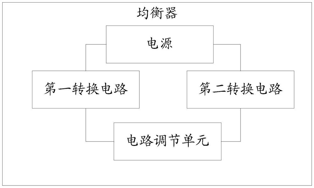
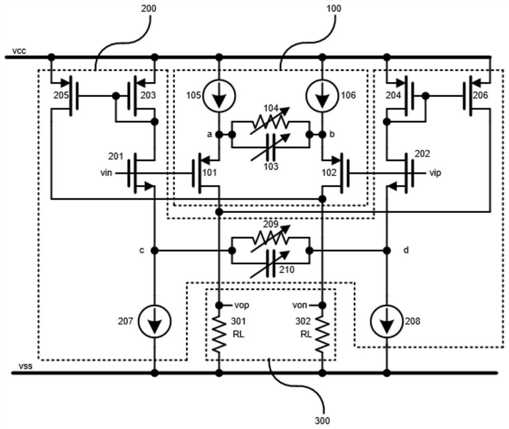
[0051] figure 1 It is a schematic diagram of the equalizer of the embodiment of the present application, such as figure 1 shown. The equalizer includes a first conversion circuit, a second conversion circuit, a circuit adjustment unit and a power supply.

[0052]The first conversion circuit is configured to convert the variation of the common-mode voltage into the variation of the differential current when the common-mode voltage input to the equalizer satisfies the working conditions of the first conversion circuit;

[0053] The second conversion circuit is configured to convert the variation of the common-mode voltage into the variation of the differential current when the common-mode voltage satisfies the working conditions of the second conversion circuit;

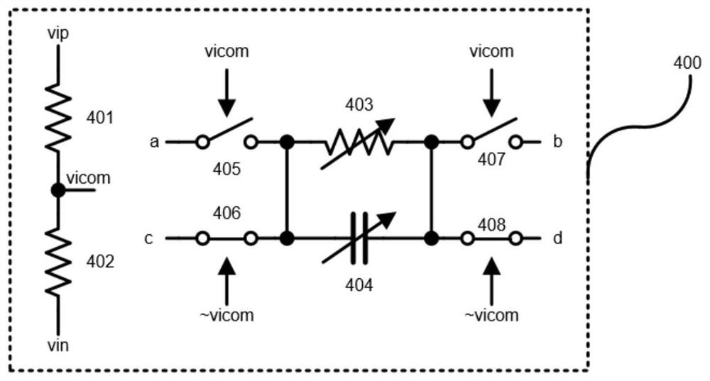
[0054] The circuit adjustment unit is configured to adjust the zero point and pole position of the first conversion circuit, and adjust the zero point and pole position of the second conversion circuit;

[0055] The...


PUM


Abstract

The invention discloses an equalizer, and the equalizer comprises: a first conversion circuit which is set to convert the variable quantity of a common-mode voltage into the variable quantity of a differential current when the common-mode voltage inputted into the equalizer meets the working condition of the first conversion circuit; a second conversion circuit which is set to convert the variable quantity of the common-mode voltage into the variable quantity of differential current when the common-mode voltage meets the working condition of the second conversion circuit; a circuit adjusting unit which is set to adjust the zero point and pole position of the first conversion circuit and adjust the zero point and pole position of the second conversion circuit; and a power supply which is set to drive the first conversion circuit and the second conversion circuit, wherein the second conversion circuit is a complementary circuit of the first conversion circuit. The working condition of the first conversion circuit and the working condition of the second conversion circuit are set to meet the condition that at least one circuit can meet the working condition at any time.

Description

technical field [0001] This article relates to the field of integrated circuit technology, especially an equalizer. Background technique [0002] The sending and receiving channels of high-speed serial data will introduce many non-ideal factors in the process of signal transmission (such as the inherent skin effect and dielectric loss of transmission media such as printed circuit board wiring, backplane wiring, and cables, etc.), these non-ideal factors The influence of factors will deteriorate as the serial data rate increases, causing the channel to exhibit low-pass characteristics in the frequency domain and attenuating the high-frequency part of the serial data. In the time domain, it is manifested as inter-symbol interference (ISI, Inter-Symbol-Interference), which deteriorates the eye diagram performance of received serial data and increases the bit error rate (BER) of received data. For the same channel, the higher the transmission rate of serial data, the greater th...

Claims


Application Information

Patent Timeline
Patent Type & Authority Applications(China)
IPC IPC(8): H04L25/02H04L25/03
CPCH04L25/0264H04L25/03878
Inventor 褚博王天心顾震宇王光春
Owner 山东高云半导体科技有限公司
Why Eureka
Try Eureka