Energy-saving deinsectization device

An energy-saving and insect-killing technology, which is applied to devices for catching or killing insects, electrical components, animal husbandry, etc.

Active Publication Date: 2021-08-17
武汉朗克环境科技有限公司
5 Cites 1 Cited by

AI-Extracted Technical Summary

Problems solved by technology

At present, there is a lack of an energy-saving disinsec...

Method used

[0031] As shown in Figure 3, preferably, the output end of the main switch W1 is connected with a purple light strip, and flies, mosquitoes, etc. have better phototaxis to purple light.
[0037] The protective plate 4 is in the shape of a blind 41, and the purpose of this design is that mosquitoes can reach the conductive grid 6 through the blind 41. In addition, the lower end of the protective plate 4 has a strip-shaped through hole 7, once the mosquito is shocked by the electric shock, the corpse will fall from the through hole 7, so as to ensure the overall cleanliness of the protective plate 4. The front of the protecti...

Abstract

The invention discloses an energy-saving deinsectization device which comprises a high-voltage pack, a detection unit, a control unit, a high-voltage oscillation unit, a boosting unit, a voltage stabilizing circuit and a power supply end; and the high-voltage pack comprises a first primary winding, a second primary winding and a secondary winding. The energy-saving deinsectization device suitable for being used in the automobile is developed for solving the problem that an electric appliance product for deinsectization in the automobile lacks in the market, and the energy-saving deinsectization device has the advantages of being capable of saving energy, environmentally friendly, free of noise and free of pollution.

Application Domain

Electric shock equipmentsInsect catchers and killers

Technology Topic

Automotive engineeringElectrical and Electronics engineering +2

Image

  • Energy-saving deinsectization device
  • Energy-saving deinsectization device
  • Energy-saving deinsectization device

Examples

  • Experimental program(1)

Example Embodiment

[0023] The specific embodiments of the present invention will be described in further detail below with reference to the accompanying drawings and embodiments. The following examples are intended to illustrate the present invention, but not to limit the scope of the present invention.
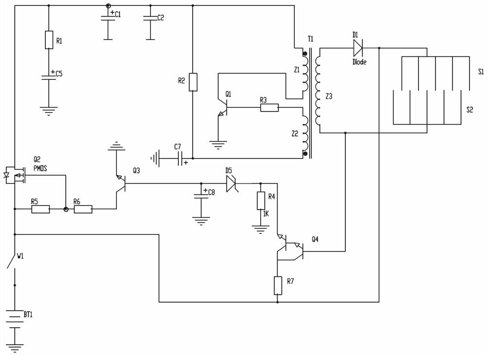
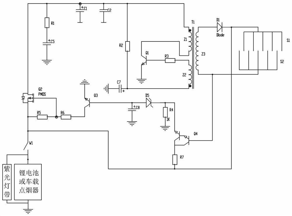
[0024] like Figure 1 to Figure 3 As shown, the energy-saving pest control device of the present invention includes a pest control circuit, and specifically includes a high-voltage package T1, a detection unit, a control unit, a high-voltage oscillation unit, a booster unit, a voltage-stabilizing circuit and a power supply terminal; the high-voltage package T1 It includes a first primary winding Z1, a second primary winding Z2 and a secondary winding Z3.
[0025] like figure 2 Specifically, the high-voltage oscillation unit includes a first primary winding Z1, a second primary winding Z2, a resistor R3, an electrolytic capacitor C7, a triode Q1 and a resistor R2, and the output end of the first primary winding Z1 is connected to the triode The collector of Q1, the base of the transistor Q1 is connected to the input end of the second primary winding Z2 through the resistor R3, the emitter of the transistor Q1 is grounded, and the output end of the second primary winding Z2 is connected to the positive electrode of the electrolytic capacitor C7 , the input end of the first primary winding Z1 is connected to a voltage regulator circuit, and the resistor R2 is connected between the input end of the first primary winding Z1 and the output end of the second primary winding Z2; the first primary winding Z1, the second The primary winding Z2 has opposite ends of the same name, so that the first primary winding Z1 and the second primary winding Z2 induce opposite voltages.
[0026] The booster unit includes a secondary winding Z3, a diode D1, an upper trigger terminal S1 and a lower trigger terminal S2, the anode of the diode D1 is connected to the output terminal of the secondary winding Z3, and the cathode of the diode D1 is connected to the upper trigger terminal S1. The lower trigger end S2 is connected to the input end of the secondary winding Z3 to form a loop;
[0027] The detection unit includes a Darlington transistor Q4, a pull-up resistor R7, a voltage regulator D5, an electrolytic capacitor C8 and a pull-down resistor R4, and the base input end of the Darlington transistor Q4 is connected to the secondary winding Z3. Input terminal; the power supply terminal is connected to the negative electrode of the diode D1, and the pull-up resistor R7 is connected between the negative electrode of the diode D1 and the collector of the Darlington tube Q4; the negative electrode of the voltage regulator tube D5 is connected to the Darlington tube Q4 The anode of the voltage regulator tube D5 is connected to the anode of the electrolytic capacitor C8; the pull-down resistor R4 is arranged between the grounding and the emitter of the Darlington tube Q4;
[0028] The control unit includes a PMOS transistor Q2, a triode Q3, a discharge resistor R5, and a voltage dividing resistor R6. The base of the triode Q3 is connected to the positive electrode of the voltage regulator D5, the base collector of the triode Q3 is connected to the voltage dividing resistor R6, and the piezoresistor R6 discharges in series. The resistor R5 is then connected to the power supply terminal, the G pole of the PMOS transistor Q2 is connected to the common terminal of the voltage resistor R6 and the discharge resistor R5, the D pole of the PMOS transistor Q2 is used as the output terminal to connect the voltage regulator circuit, and the S pole of the PMOS transistor Q2 is connected to the power supply terminal. The turn-on condition of the PMOS tube is |VGS|>Vt, that is, the voltage difference between the two ends of the PMOS tube G-S is greater than the turn-on voltage Vt. The function of the discharge resistor R5 and the voltage divider resistor R6 in this circuit is to provide the voltage difference between the two ends of the G-S. In addition, the parasitic capacitance of the PMOS tube needs to be considered, so when the PMOS tube is turned off, the discharge resistor R5 is required to discharge the parasitic capacitance. The PMOS tube has the characteristics of fast turn-on and turn-off, no noise, and low power consumption, which meets the current requirements for energy conservation and emission reduction.
[0029] The voltage-stabilizing circuit includes a capacitor C1, a capacitor C2, a capacitor C5 and a resistor R1; the resistor R1 and the capacitor C5 are connected in series, and the capacitor C1 and the capacitor C2 are connected in parallel. Capacitors C2 and C5 are point solution capacitors, so they can be used for good voltage regulation and energy storage.
[0030] The power output terminal is provided with a main switch W1.
[0031] like image 3 As shown, preferably, the output end of the main switch W1 is connected with a violet light strip, and flies, mosquitoes, etc. have better phototaxis to violet light.
[0032] Preferably, the power source is a 12V lithium battery BT1 or a power source connected to a car cigarette lighter.
[0033] Preferably, the resistance ratio of the discharge resistor R5 to the voltage divider resistor R6 is 1:1, and the resistance values ​​of the discharge resistor R5 and the voltage divider resistor R6 are between 1K and 2K.
[0034] Working principle: The main switch is turned on. At this time, if there is no insect contacting the upper trigger terminal and the lower trigger terminal, the upper trigger terminal and the lower trigger terminal are in a floating state, and the detection circuit does not work, so the whole circuit is in a non-conductive standby state. , greatly reducing standby power consumption. If the insect contacts the upper trigger terminal and the lower trigger terminal, the upper trigger terminal and the lower trigger terminal generate resistance, and the base of the Darlington tube Q4 and the main switch are turned on, so that the Darlington tube Q4 is turned on, and the voltage regulator tube D5 is broken down. Output the turn-on voltage of the voltage regulator tube D5 (generally, the voltage regulator tube is selected as a 57 series tube with a turn-on voltage of 5-6V), thereby triggering the turn-on of the transistor Q3, and the electrolytic capacitor C8 here acts as a delay switch. The conduction of the transistor Q3 leads to the conduction of the resistors R5 and R6. Due to the voltage division principle, the G-S pole of the PMOS tube Q2 generates a voltage difference, so that the PMOS tube is turned on. After the voltage supply voltage is stabilized by the voltage regulator circuit, it is input to The high-voltage oscillation unit, at this time, the circuit is divided into two circuits, one of which charges the electrolytic capacitor C7 through the resistor R2, and enters the base of the transistor Q1 through the second primary winding Z2 and the resistor R3. As the voltage of the electrolytic capacitor C7 rises, the base of the transistor Q1 The pole is turned on, the power supply voltage reaches the transistor Q1 through the first primary winding Z1 and then is grounded to form a loop, the first primary winding Z1 is connected to the upper positive and lower negative voltages, at this time, the second primary winding Z2 and the secondary winding Z3 are induced Output voltage, among which the second primary winding Z2 due to the relationship of the same name terminal, the second primary winding Z2 induces a voltage of upper negative and lower positive, so that the base voltage of the transistor Q1 drops to the cutoff, after the cutoff, the electrolytic capacitor C7 is charged, and continues to make the base of the transistor Q1 The pole is turned on, and in such a state of continuous on and off, oscillation is formed; in the continuous oscillation process, the secondary winding Z3 induces a high voltage, so that the upper trigger terminal S1 and the lower trigger terminal S2 generate high voltage, and the mosquitoes are in the electrocuted at high voltage.
[0035] In addition, for practical use, the inventor also designed a practical device that can be plugged into the air outlet, and the device accommodates the above-mentioned insect control circuit. For details, please refer to Figure 4 and Figure 5.
[0036]The device specifically includes a casing 1, an air outlet clip 2, one end of the air outlet clip 2 is tapered, and the other end is provided with a universal ball head 3, and the back of the casing 1 is provided with a ball head matched with the universal ball head 3 Block 31. The front end of the housing 1 is provided with a protective plate 4 to prevent the user from touching the inner conductive mesh 6 . A circuit board 5 is provided inside the casing 1, and the circuit board 5 is the carrier of the above-mentioned insect control circuit. At the front end of the circuit board 5, there is a conductive mesh 6. The conductive mesh 6 actually has two layers, and the outer layer 61 is connected to the trigger terminal S2. , the inner layer 62 contacts the sending end S1. The reason for this setting is that the triggering end S2 is the negative electrode. When the body of the worm is only in contact with S2, it will not conduct electricity, and it must further contact the inner layer S1 to form a loop, thereby triggering the high-voltage oscillation unit to achieve The high voltage output makes the insects get electric shock; in addition, the outer layer of the negative electrode and the inner layer of the positive electrode also improve the safety and prevent users from getting electric shock.
[0037] The protective plate 4 is in the shape of a louver 41 , and the purpose of this design is that mosquitoes can reach the conductive mesh 6 through the louver 41 . In addition, the lower end of the protective plate 4 has a through hole 7 in the shape of a long strip. Once the mosquitoes are electrocuted, the corpse will fall from the through hole 7 to ensure the overall cleanliness of the protective plate 4 . The front of the protective plate 4 is inclined downward. On the one hand, most of the mosquitoes are located on the bottom surface of the vehicle. This design can make it easier for the mosquitoes to enter. In addition, the body after being electrocuted will roll off the inclined surface and will not gather. It is also not easy to accumulate dust, which ensures the cleaning of the protective plate 4 .
[0038] In order to better attract mosquitoes, a bait slot 8 is provided on any side of the circuit board 5, and a bait for attracting mosquitoes is placed inside, thereby improving the efficiency of insect eradication.
[0039] Aiming at the pain point that the market lacks an electrical product aimed at killing insects in cars, the invention develops an energy-saving insect killing device suitable for use in cars, which has the characteristics of energy saving, environmental protection, no noise and no pollution.
[0040] To sum up, the above-mentioned embodiments are not limiting embodiments of the present invention, and any modifications or equivalent deformations made by those skilled in the art on the basis of the essential content of the present invention are all within the technical scope of the present invention.

PUM

no PUM

Description & Claims & Application Information

We can also present the details of the Description, Claims and Application information to help users get a comprehensive understanding of the technical details of the patent, such as background art, summary of invention, brief description of drawings, description of embodiments, and other original content. On the other hand, users can also determine the specific scope of protection of the technology through the list of claims; as well as understand the changes in the life cycle of the technology with the presentation of the patent timeline. Login to view more.
Why Eureka
Try Eureka