Gas suction device

An inhalation device and gas technology, applied in respirator, breathing mask and other directions, can solve the problems of decreased treatment effect, user discomfort, and excessive A gas escape, and achieve a better user experience.

Pending Publication Date: 2021-08-17
SHENZHEN YUMI INFO CO LTD
View PDF0 Cites 1 Cited by
  • Summary
  • Abstract
  • Description
  • Claims
  • Application Information

AI Technical Summary

Problems solved by technology

[0002] At present, the treatment method of gas inhalation (assisted breathing) is widely used in hospitals and families. The treatment process is: connect the machine (such as: ventilator) with the medical mask, the user wears the medical mask, and the medical mask is closely attached to the user's face. To cover the mouth and nose of the user, the machine first passes the A gas into the medical mask, the user inhales the A gas by inhaling, and exhales the B gas into the medical mask; the following problems exist in the use of the medical mask: the A gas provided by the machine (such as : Oxygen), mixed with the B gas exhaled by the user {B gas includes nitrogen, oxygen, carbon dioxide and a small amount of inert gas (argon, krypton, xenon, neon, helium, etc.)} mixed in the medical mask, the mixture will cause A gas Concentration decreases, resulting in decreased therapeutic effect
[0004] 1. If the small holes are made too large or too many, the A gas provided by the machine will escape more and fail to reach the preset concentration;
[0005] 2. If the small hole is made too small, the gas B exhaled by the user will not be discharged smoothly, and it will accumulate in the medical mask and mix with gas A, resulting in a decrease in the concentration of gas A. At the same time, if the small hole is made too small, Also increases the air pressure inside the medical mask, making the user uncomfortable

Method used


Image

  • Gas suction device
  • Gas suction device
  • Gas suction device

Examples


Embodiment Construction

[0025] In order to describe the technical solution of the present invention more clearly and completely, the present invention will be further described below in conjunction with the accompanying drawings.

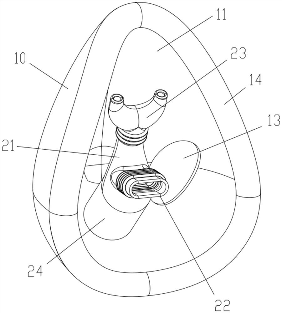
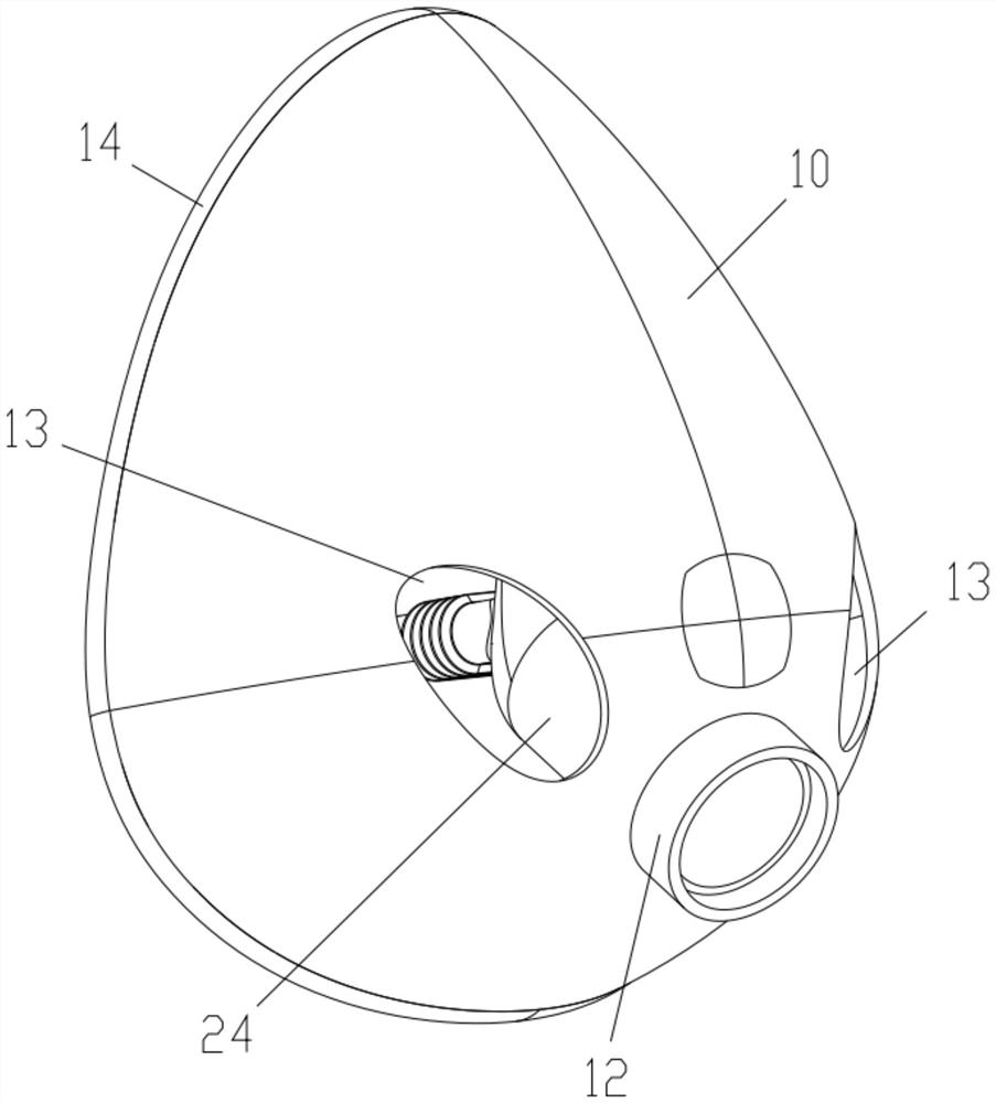
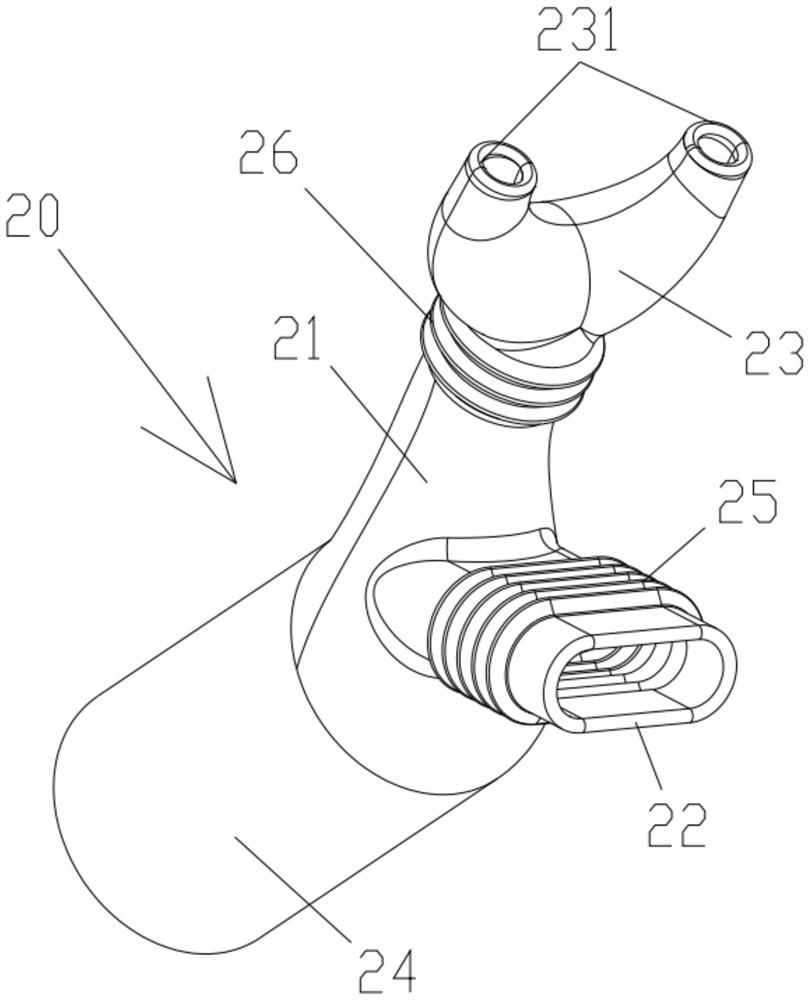
[0026] Please refer to Figure 1 to Figure 3 The present invention proposes a gas inhalation device, the gas inhalation device includes a cover 10 and a drainage assembly 20, the cover 10 is bent to form a storage cavity 11, the drainage assembly 20 is accommodated in the storage cavity 11, the The drainage assembly 20 includes a main body 21, a suction part 22 and a suction part 23, the suction part 22 and the suction part 23 communicate with the main body 21 respectively, and the suction part 22 can be relatively The main body 21 is stretchable and / or bendable, and the nasal suction part 23 can be stretchable and / or bendable relative to the main body 21 .

[0027] Further, the nasal suction part 23 is provided with two air outlets 231 communicating with the nasal suctio...


PUM


Abstract

The invention provides a gas suction device, which comprises a cover body and a drainage assembly, the cover body is bent to form a containing cavity, the drainage assembly is contained in the containing cavity, the drainage assembly comprises a main body, a mouth inhalation part and a snuffing part, the mouth inhalation part and the snuffing part are communicated with the main body, the mouth inhalation part can stretch out and draw back and / or bend relative to the main body, the snuffing part can stretch out and draw back and / or bend relative to the main body, and two air outlet parts communicated with the snuffing part are arranged on the snuffing part; when a user wears and uses the gas suction device, the position of the mouth inhalation part is adjusted to enable the mouth inhalation part to be located near the mouth or in the mouth, the position of the snuffing part is adjusted to enable the two gas outlet parts to be located below the two nares or in the two nares respectively, gas provided by an external machine is directly inhaled by the user through the mouth inhalation part and the gas outlet parts, and the concentration of the gas cannot be reduced.

Description

technical field [0001] The invention relates to the field of medical accessories, in particular to a gas inhalation device. Background technique [0002] At present, the treatment method of gas inhalation (assisted breathing) is widely used in hospitals and families. The treatment process is: connect the machine (such as: ventilator) with the medical mask, the user wears the medical mask, and the medical mask is closely attached to the user's face. To cover the mouth and nose of the user, the machine first passes the A gas into the medical mask, the user inhales the A gas by inhaling, and exhales the B gas into the medical mask; the following problems exist in the use of the medical mask: the A gas provided by the machine (such as : Oxygen), mixed with the B gas exhaled by the user {B gas includes nitrogen, oxygen, carbon dioxide and a small amount of inert gas (argon, krypton, xenon, neon, helium, etc.)} mixed in the medical mask, the mixture will cause A gas Concentration...

Claims


Application Information

Patent Timeline
Patent Type & Authority Applications(China)
IPC IPC(8): A61M16/06
CPCA61M16/0666A61M16/0683A61M16/0672
Inventor 张雪莲张诚李彩霞
Owner SHENZHEN YUMI INFO CO LTD
Why Eureka
Try Eureka