Electric automatic feed mixing device

A technology of electrical automation and mixing device, which is applied in the direction of feed, mixer, mixer with rotary mixing device, etc. Mixing and other problems, to achieve the effect of good mixing and crushing, reducing labor and saving costs

A technology of electrical automation and mixing device, which is applied in the direction of feed, mixer, mixer with rotary mixing device, etc. Mixing and other problems, to achieve the effect of good mixing and crushing, reducing labor and saving costs

CN113262697AInactive Publication Date: 2021-08-17ZHOUKOU NORMAL UNIV

Image

  • Electric automatic feed mixing device
  • Electric automatic feed mixing device
  • Electric automatic feed mixing device

Examples


Embodiment 1

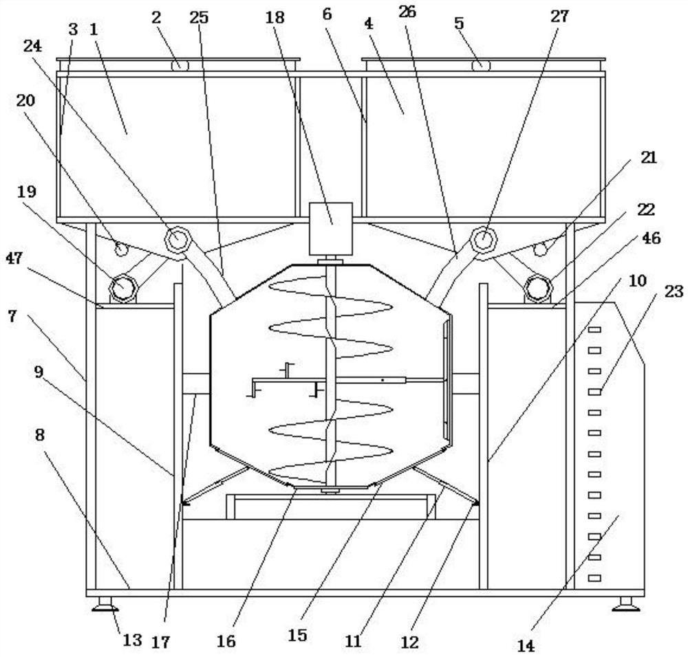
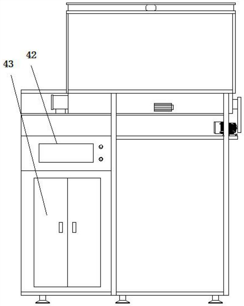
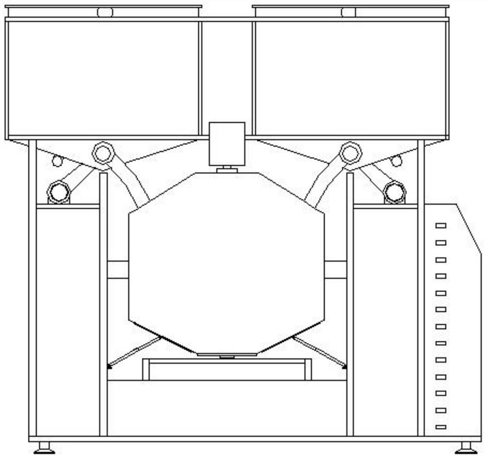
[0017] Such as Figure 1-Figure 7 Shown:

[0018]The electric automation feed mixing device is characterized in that the bottom bracket 8 is provided with symmetrical vertical plates I9 and vertical plates II10, and the vertical plates I9 and vertical plates II10 are connected to the stirring device through the connecting rod 17, and the stirring device includes a motor I18 And the stirring box 16, the motor I18 is located in the middle position directly above the stirring box 16, the motor I18 is connected to the top of the rotating shaft 29, and the bottom of the rotating shaft 29 is connected to the bearing seat 31, and the motor I18 drives the rotating shaft 29 to rotate, and the rotation The upper and lower parts of the shaft 29 are respectively provided with mutually symmetrical helical pieces I28 and helical piece II30. The helical piece I28 and the helical piece II30 transport the material 45 to the middle position of the mixing box 16 respectively, and stir while conv...

Embodiment 2

[0020] Such as Figure 1-Figure 7 Shown:

[0021] The electric automation feed mixing device is characterized in that the bottom bracket 8 is provided with symmetrical vertical plates I9 and vertical plates II10, and the vertical plates I9 and vertical plates II10 are connected to the stirring device through the connecting rod 17, and the stirring device includes a motor I18 And the stirring box 16, the motor I18 is located in the middle position directly above the stirring box 16, the motor I18 is connected to the top of the rotating shaft 29, and the bottom of the rotating shaft 29 is connected to the bearing seat 31, and the motor I18 drives the rotating shaft 29 to rotate, and the rotation The upper and lower parts of the shaft 29 are respectively provided with mutually symmetrical helical pieces I28 and helical piece II30. The helical piece I28 and the helical piece II30 transport the material 45 to the middle position of the mixing box 16 respectively, and stir while con...


PUM


Abstract

The invention discloses an electric automatic feed mixing device, and belongs to the technical field of electrified equipment. The bottom support is provided with a vertical plate I and a vertical plate II which are symmetrical, the vertical plate I and the vertical plate II are connected through a connecting rod and a stirring device, the stirring device comprises a motor I and a stirring box body, the motor I is located in the middle position over the stirring box body, the motor I is connected with the rotating shaft, the upper part and the lower part of the rotating shaft are respectively provided with a spiral sheet I and a spiral sheet II which are mutually symmetrical, the spiral sheet I and the spiral sheet II respectively convey materials to the middle position of the stirring box body, and the middle position of the rotating shaft is respectively provided with a crushing device and a scraping device; a feed box frame I and a feed box frame II which are symmetrical are further arranged on the feed box supporting frame, a feed box I and a feed box II are arranged in the feed box frame I and the feed box frame II respectively, the technical problems that existing equipment cannot be operated intelligently and is poor in stirring effect are solved, and the device is mainly applied to the aspect of feed mixing.

Description

technical field [0001] The invention belongs to the technical field of electric automation equipment, and in particular relates to an electric automation feed mixing device. Background technique [0002] Patent application number CN201810497608.8 discloses an electric automation feed mixing device, including a bracket and a top plate, a panel is installed in the middle of the right side of the bracket, and a solenoid valve switch, switch B and Switch A, the bottom of the panel is connected with wires, the top plate is placed horizontally on the top of the support, and the middle of the bottom end of the top plate is vertically connected with a stirring tank. The present invention is provided with feeding tubes at the left and right ends of the top of the top plate, and a screw feeding rod is arranged in the feeding tube, which facilitates preliminary elimination of the added larger agglomerated feed and improves the effect of feed mixing in the later stage. Since the conica...

Claims


Application Information

Patent Timeline
17 Aug 2021
Publication
CN113262697A
IPC
B01F13/10; B01F15/00; B01F15/02; B01F15/04; A23N17/00; A23N17/02; B01F7/24
CPC
A23N17/007; A23N17/02; B01F27/92; B01F33/833; B01F33/83612; B01F35/123; B01F35/22; B01F35/71775
Inventors
罗刘敏; 尚才