High-voltage telegraph pole capable of being adjusted in a self-balance mode

A self-balancing technology for utility poles, applied in animal repellants, applications, building types, etc., can solve problems such as short circuit of high-voltage lines, breakage of high-voltage lines, tilting or overturning of utility poles, etc., to reduce gravity, prevent crushing, The effect of improving stability

Inactive Publication Date: 2021-08-17
寇旭
View PDF0 Cites 2 Cited by
  • Summary
  • Abstract
  • Description
  • Claims
  • Application Information

AI Technical Summary

Problems solved by technology

[0005] The purpose of the present invention is to solve the problems that utility poles tend to roll or overturn in areas with strong winds, and rain and snow accumulate on high-voltage lines in winter, which may easily cause high-voltage lines to break and birds to build nests on high-voltage lines, which may easily lead to short-circuiting of high-voltage lines. A self-balancing and adjustable high-voltage utility pole

Method used


Image

  • High-voltage telegraph pole capable of being adjusted in a self-balance mode
  • High-voltage telegraph pole capable of being adjusted in a self-balance mode
  • High-voltage telegraph pole capable of being adjusted in a self-balance mode

Examples


Embodiment 1

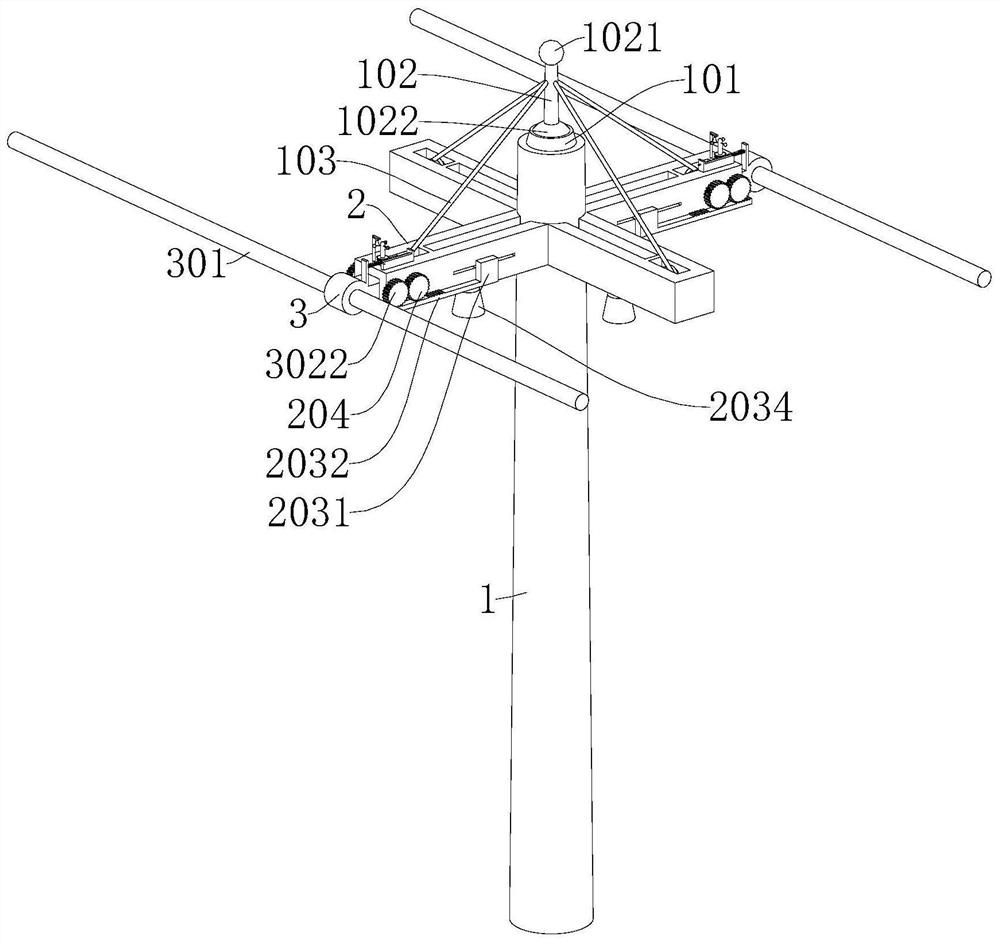
[0033] refer to Figure 1-5 , a high-voltage utility pole capable of self-balancing adjustment, comprising a utility pole body 1, a balance mechanism is arranged on the utility pole body 1, a clearing mechanism is arranged on the balance mechanism, and an expulsion mechanism is arranged on the clearing mechanism.

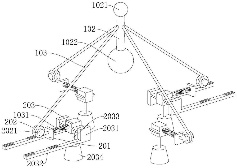
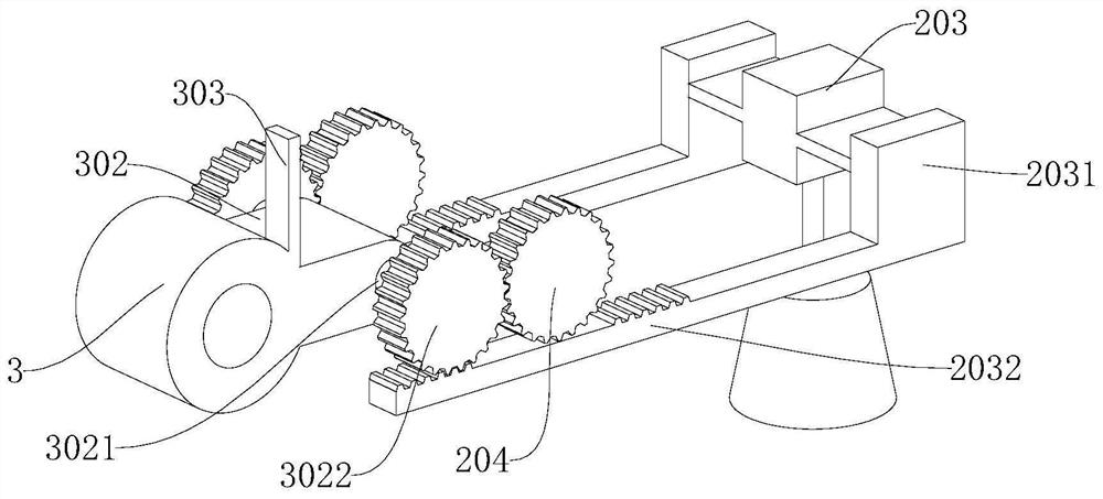
[0034] Use this device in areas with high wind force. When the wind blows, the wind blows the wind direction rod 102, and the wind direction rod triggers the balance mechanism to work. The counterweight 2034 slides in the opposite direction to the wind direction, and the center of gravity of the utility pole body 1 moves toward the counterweight 2034. move in the direction to counteract the wind force and improve the stability of the utility pole body 1. When the counterweight 2034 moves, the clearing mechanism works, and the installation ring 3 swings up and down, driving the high-voltage wire 301 connected in the installation ring 3 to shake, and the high-voltage w...

Embodiment 2

[0042] refer to figure 1 and Figure 4 , is basically the same as Embodiment 1, furthermore, the second rack 402 is fixedly connected with a slider 4021, and the mounting seat 4 is provided with a chute to cooperate with the slider 4021, and the second rack 402 is far away from the guide rod. One end of 4022 has rounded corners, and the L-shaped pole 503 is fixedly connected on the mounting frame 2, and the bell 5031 is fixedly connected on the L-shaped pole 503, and the semicircle block 5021 contacts with the bell 5031 intermittently.

[0043] The chamfer on the second rack 402 enables the shifting block 303 to reduce the friction between the shifting block 3 and the second rack 402 when it is pushed, so that the swing resistance of the mounting ring 3 is reduced, and the semicircle block 5021 When rotating, the bell 5031 will be touched intermittently, so that the semicircular block 5021 hits the bell 5031, making the bell 5031 make a sound, which will frighten the birds an...


PUM


Abstract

The invention discloses a high-voltage telegraph pole capable of being adjusted in a self-balance mode, and belongs to the technical field of electric power transmission. The high-voltage telegraph pole capable of being adjusted in a self-balance mode comprises a telegraph pole body, a balance mechanism is arranged on the telegraph pole body, a clearing mechanism is arranged on the balance mechanism, and an expelling mechanism is arranged on the clearing mechanism. By arranging the balance mechanism, the device is used in an area with high wind power, when wind blows, the wind power blows a wind direction rod, the wind direction rod triggers the balance mechanism to work, the wind power is counteracted, the stability of the telegraph pole body is improved, by arranging the clearing mechanism, a mounting ring swings up and down to drive a high-voltage line connected in the mounting ring to swing, accumulated snow or frozen ice on the high-voltage line is shaken off, gravity borne by the high-voltage line is reduced, the high-voltage line is prevented from being broken, by arranging the expelling mechanism, birds are expelled, a bell makes a sound to enhance the expelling effect when a semicircular block is in contact with the bell during rotation, the birds are prevented from nesting on the high-voltage line, and then the possibility of short circuit is reduced.

Description

technical field [0001] The invention relates to the technical field of power transmission, in particular to a self-balancing and adjustable high-voltage utility pole. Background technique [0002] With the continuous development of the power communication network, the erection of high-voltage utility poles is an infrastructure project to ensure the smooth flow of the power grid. [0003] In order to supply power to different areas, the high-voltage utility poles need to be installed in different areas. In windy and strong wind areas, the utility poles may tilt if they are blown by the wind for a long time. In severe cases, they may fall over, which will cause the high-voltage lines to be pulled and broken. , and when it rains or snows in winter, especially in freezing weather after rain or snow, the snow piled up on the high-voltage cables or the ice attached to the high-voltage cables due to low temperature freezes will aggravate the high-voltage cables or The bearing burd...

Claims


Application Information

Patent Timeline
Patent Type & Authority Applications(China)
IPC IPC(8): E04H12/00E04H12/18A01M29/16A01M29/08
CPCA01M29/08A01M29/16E04H12/00E04H12/18
Inventor 寇旭李星星何舟
Owner 寇旭
Why Eureka
Try Eureka