
Design method for surface rigidity of bumper assembly

A design method and bumper technology, applied in design optimization/simulation, special data processing applications, geometric CAD, etc., can solve the problems of low development efficiency, high development cost, and inappropriate surface stiffness of bumper assemblies for passenger cars. , to achieve the effect of reducing product development cost, reasonable structural simulation model, and improving simulation analysis accuracy

Active Publication Date: 2021-08-17
CHINA FIRST AUTOMOBILE
View PDF12 Cites 0 Cited by
  • Summary
  • Abstract
  • Description
  • Claims
  • Application Information

AI Technical Summary

Problems solved by technology

[0004] Based on the above, the purpose of the present invention is to provide a design method for the surface stiffness of the bumper assembly, which solves the low development efficiency of passenger cars caused by the inappropriate surface stiffness of the bumper assembly in the prior art. and high development costs

Method used


Image

  • Design method for surface rigidity of bumper assembly
  • Design method for surface rigidity of bumper assembly

Examples


Embodiment 1

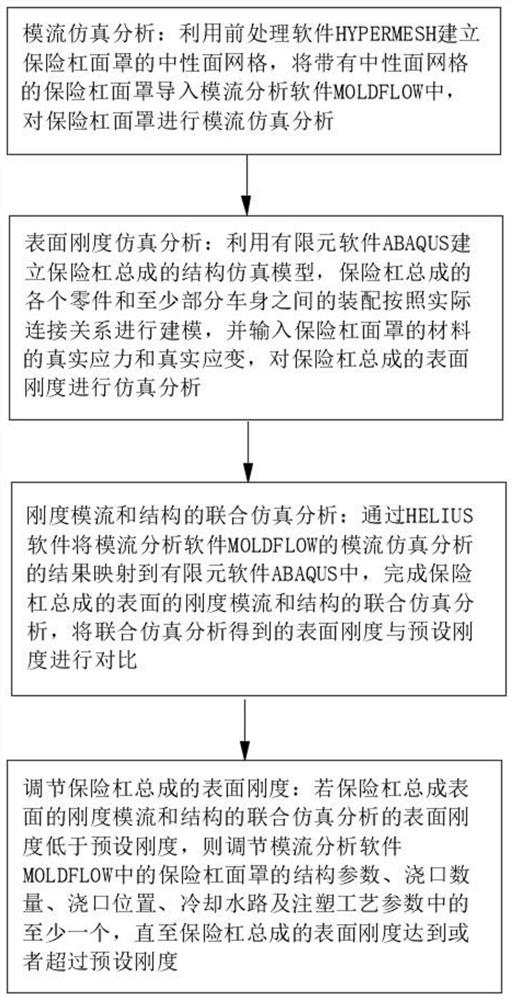
[0039] This embodiment provides a design method for the surface stiffness of the bumper assembly, such as figure 1 shown, including:

[0040] Mold flow simulation analysis: Use the pre-processing software HYPERMESH to establish the neutral plane grid of the bumper face, import the bumper face with the neutral plane grid into the mold flow analysis software MOLDFLOW, and conduct mold flow simulation analysis on the bumper face ;

[0041] Surface stiffness simulation analysis: use the finite element software ABAQUS to establish the structural simulation model of the bumper assembly, the assembly between each part of the bumper assembly and at least part of the body is modeled according to the actual connection relationship, and the material of the bumper mask is input The real stress and real strain of the bumper assembly are simulated and analyzed;

[0042] Co-simulation analysis of stiffness mold flow and structure: through HELIUS software, the results of mold flow simulatio...

Embodiment 2

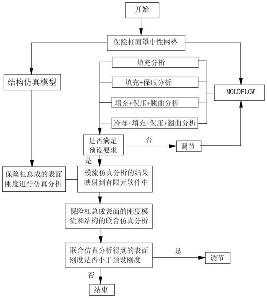
[0071] The design method of the surface stiffness of the bumper assembly provided in this embodiment, such as figure 2 shown, including:

[0072] S1. Mold flow simulation analysis:

[0073] S11, using the pre-processing software HYPERMESH to establish the neutral plane mesh of the bumper mask;

[0074] S12. Import the bumper mask with the neutral plane mesh into the mold flow analysis software MOLDFLOW;

[0075] S13. Carry out grid modeling for the gating system of the bumper mask: the flow channel of the gating system is modeled with a column unit, the gate is a cold gate, and the injection molding process parameters are set;

[0076] S14. Carrying out grid modeling on the cooling water channel: setting the parameters of the cooling water channel;

[0077] S15. Select the material of the bumper face cover, and determine the PVT characteristic curve, viscosity curve and residual stress correction algorithm model in the bumper face cover of the material;

[0078] S16. Carr...


PUM


Abstract

The invention relates to the technical field of bumper assembly design, and discloses a design method for surface rigidity of a bumper assembly, which comprises the following steps: establishing a neutral surface grid of a bumper mask by using HYPERMESH, and importing the neutral surface grid into MOLDFLOW; establishing a structure simulation model by utilizing ABAQUS, and performing simulation analysis on the surface rigidity of the bumper assembly; mapping the result of the mold flow simulation analysis of the MOLDFLOW to ABAQUS through HELIUS, and completing joint simulation analysis of the rigidity mold flow and the structure of the surface of the bumper assembly; and adjusting at least one of the structural parameters of the bumper mask, the number of sprues, the positions of the sprues, the cooling water channel and the injection molding process parameters till the surface rigidity of the bumper assembly reaches or exceeds the preset rigidity. According to the design method disclosed by the invention, the problems of low development efficiency and high development cost of the passenger car caused by improper surface rigidity of the bumper assembly in the prior art are solved.

Description

technical field [0001] The invention relates to the technical field of bumper assembly design, in particular to a design method for the surface stiffness of the bumper assembly. Background technique [0002] With the demand for lightweight automobiles and the increasing importance of automobile styling, "replacing steel with plastic" has become one of the important directions for the development of lightweight automobiles. Its advantages are light weight, high integration, and free modeling to satisfy consumers. For the pursuit of individuality, the manufacturing of plastic parts has higher requirements than traditional metal parts manufacturing: reasonable part structure, reasonable selection of injection molding materials, reasonable gating system, cooling system design, reasonable injection molding process parameters, molding After good appearance and exact size etc. [0003] For a relatively large injection molded part such as a passenger car bumper assembly, the mold c...

Claims


Application Information

Patent Timeline
IPC IPC(8): G06F30/15G06F30/23
CPCG06F30/15G06F30/23Y02T90/00
Inventor 于保君肖永富杜伟娟高猛刘海朱学武张雨刘闯
Owner CHINA FIRST AUTOMOBILE
Learn More