
Multi-electron-beam traveling wave tube with axisymmetric folded waveguide high-frequency slow wave structure

A folded waveguide and slow-wave structure technology, applied in traveling wave tubes, transit-time electron tubes, discharge tubes, etc., can solve the problem of poor stability and reliability of the electrical parameters of traveling wave tubes, and the difficulty of generating and transmitting flat ribbon electron beams. , small output power of the traveling wave tube, etc., to achieve the effect of reducing the space charge effect, reducing the radial component, and increasing the total current

Pending Publication Date: 2021-08-17
深圳奥镨科技有限公司
View PDF0 Cites 1 Cited by
  • Summary
  • Abstract
  • Description
  • Claims
  • Application Information

AI Technical Summary

Problems solved by technology

[0003] 1. The planar folded waveguide structure can carry relatively small microwave power;
[0004] 2. The energy carried by the single injection electron beam is small, resulting in a small output power of the traveling wave tube;
[0005] 3. It is difficult to generate and transmit flat ribbon electron beams, and the stability and reliability are poor
[0006] Among them, the microwave power that the planar folded waveguide structure can carry is relatively small and the energy that a single electron beam can provide is relatively small, which is the first problem that needs to be solved in the existing folded waveguide high-frequency slow wave module, and the planar ribbon electron beam is difficult to generate And transmission, poor stability and reliability, and poor stability and reliability of electrical parameters of traveling wave tubes using planar electron beams, which are further problems that need to be solved for existing folded waveguide high-frequency slow-wave modules

Method used


Image

  • Multi-electron-beam traveling wave tube with axisymmetric folded waveguide high-frequency slow wave structure
  • Multi-electron-beam traveling wave tube with axisymmetric folded waveguide high-frequency slow wave structure
  • Multi-electron-beam traveling wave tube with axisymmetric folded waveguide high-frequency slow wave structure

Examples


Embodiment Construction

[0028] In order to make the object, technical solution and advantages of the present invention clearer, the present invention will be further described in detail below in conjunction with the accompanying drawings and embodiments. It should be understood that the specific embodiments described here are only used to explain the present invention, not to limit the present invention.

[0029] It should be noted that, when an element is referred to as being “mounted on”, “fixed on” or “disposed on” another element, it may be directly on the other element or there may be an intervening element at the same time. When an element is referred to as being "connected to" another element, it can be directly connected to the other element or intervening elements may also be present.

[0030] It should also be noted that the orientation terms such as left, right, up, and down in the embodiments of the present invention are only relative concepts or refer to the normal use state of the produ...


PUM


Abstract

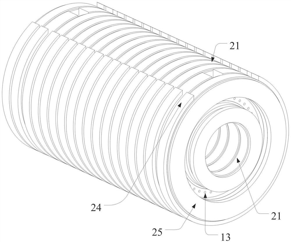
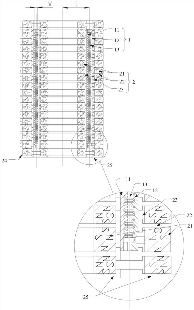
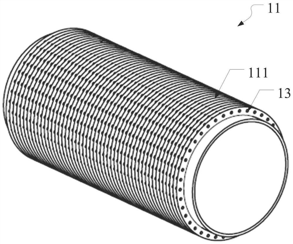
The invention discloses a multi-electron-beam traveling wave tube of an axisymmetric folded waveguide high-frequency slow wave structure. The multi-electron-beam traveling wave tube comprises an axisymmetric folded waveguide module and a coaxial periodic magnet focusing system arranged on the axisymmetric folded waveguide module, the axisymmetric folded waveguide module comprises an inner conductor and an outer conductor, and the outer conductor is sleeved outside the inner conductor. Outer fins are arranged on the outer wall of the inner conductor, inner fins are arranged on the inner wall of the outer conductor, the outer fins and the inner fins are embedded in a staggered manner to form the axisymmetric folded waveguide structure, and the inner conductor and the outer conductor are each provided with a plurality of electron beam channels. Through multiple electron beams, the space charge effect can be reduced, the total current is increased, and the microwave output power is increased. According to the present invention, the working frequency is improved through a high-order electromagnetic wave mode in the axial symmetry folded waveguide in the circumferential direction; the coaxial periodic magnet focusing system is beneficial to improving the axial component of a magnetic field in an electron beam channel and reducing the radial component, so that the electron beams can be transmitted more easily.

Description

technical field [0001] The invention relates to the technical field of microwave vacuum devices, in particular to a multi-electron injector traveling wave tube with an axisymmetric folded waveguide high-frequency slow-wave structure. Background technique [0002] The existing folded waveguide high-frequency slow-wave modules generally adopt planar folded waveguide structures and single-shot cylindrical or ribbon electron beams. Such folded waveguide high-frequency slow-wave modules have the following disadvantages: [0003] 1. The planar folded waveguide structure can carry relatively small microwave power; [0004] 2. The energy carried by the single injection electron beam is small, resulting in a small output power of the traveling wave tube; [0005] 3. It is difficult to generate and transmit flat ribbon-shaped electron beams, and the stability and reliability are poor. [0006] Among them, the microwave power that the planar folded waveguide structure can carry is re...

Claims


Application Information

Patent Timeline
Patent Type & Authority Applications(China)
IPC IPC(8): H01J25/48H01J23/087
CPCH01J25/48H01J23/087
Inventor 陈涛
Owner 深圳奥镨科技有限公司
Learn More