Contact chip regenerating device and contact chip regenerating method

A technology of regeneration device and contact tip, applied in electrode accessories, other household appliances, hollow objects, etc., can solve the problems of unstable contact state, unstable welding current, and reduced welding quality, and achieve stable welding quality and low cost. Effect

Active Publication Date: 2021-08-17
TIPMAN
View PDF11 Cites 0 Cited by
  • Summary
  • Abstract
  • Description
  • Claims
  • Application Information

AI Technical Summary

Problems solved by technology

[0003] However, if arc welding is repeated, the tip side inner peripheral surface of the guide hole on the contact tip is worn due to friction with the welding wire, resulting in an increase in the diameter of the guide hole on the tip side of the contact tip.
In this way, the position of the welding wire in the guide hole is easy to change during arc welding, and the contact state between the welding wire and the inner peripheral surface of the guide hole is unstable, so the welding current flowing from the contact tip to the object to be welded through the welding wire becomes unstable. This in turn will lead to a decrease in welding quality
Therefore, the contact tip that has undergone repeated arc welding is usually removed from the welding torch and replaced periodically, but there is a problem that the cost of the parts increases

Method used


Image

  • Contact chip regenerating device and contact chip regenerating method
  • Contact chip regenerating device and contact chip regenerating method
  • Contact chip regenerating device and contact chip regenerating method

Examples


Embodiment approach 1

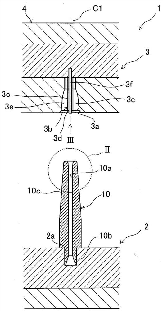
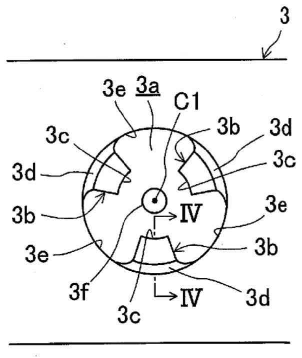
[0083] figure 1 It is a schematic cross-sectional view of the contact tip regeneration device 1 according to Embodiment 1 of the present invention. The contact tip regenerating device 1 is a device for regenerating a copper contact tip 10 mounted on an arc welding torch (not shown) after use, and includes: a first mold 2 capable of fixing the contact tip 10; The first mold 3 is placed opposite to the second mold 3 above it, and the press 4 is used to move the first mold 2 and the second mold 3 closer to or farther away from each other by raising and lowering the second mold 3 relative to the first mold 2 . .

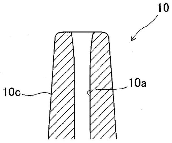
[0084] The contact tip 10 is in the shape of an elongated rod. The outer peripheral surface of the contact tip 10 has a main body portion 10c whose diameter gradually decreases linearly from the middle portion to the tip.

[0085] On the base end side of the contact tip 10, an approximately cylindrical external thread portion 10b protrudes, and a guide hole 10a with a ...

Embodiment approach 2

[0113] Figure 11 A contact tip regeneration device 1 according to Embodiment 2 of the present invention is shown. In this Embodiment 2, the details of devices other than the first mold 2 and the second mold 3 are disclosed. The first mold 2 and the second mold 3 are the same as Embodiment 1, so only the differences from Embodiment 1 are discussed below. to explain.

[0114] Such as Figure 11 and Figure 12 As shown, the contact tip regeneration device 1 according to Embodiment 2 includes a main body frame 5 serving as the skeleton of the contact tip regeneration device 1 , and a protective cover 1 a covering the entire main body frame 5 .

[0115] The protection cover 1a has an approximately semicircular cross-section on the front side of the device, and the protection cover 1a is in the shape of a box extending up and down, and an operation panel 1b for operating the contact tip regeneration device 1 is provided on the upper part.

[0116] The main body frame 5 has an u...


PUM


Abstract

A device (1) is provided with a first die (2), a second die (3), and a press machine (4). The second die (3) has a plastic processing hole (3a) in which a core metal (3f) is arranged on a hole center line (C1). The plastic processing hole (3a) has an inner circumferential surface on which three ridges (3b) are provided at regular intervals in the circumferential direction of the hole center line (C1). As the first and second dies (2), (3) are moved closer to each other, the core (3f) is inserted into the guide hole (10a) of the contact chip (10) and the ridges (3b) cause the tip-end side of the contact chip (10) to be pressed and plastically deformed until coming into contact with the core (3f).

Description

technical field [0001] The present invention relates to a contact tip regeneration device and a contact tip regeneration method for regenerating a contact tip whose tip-side inner peripheral surface of a guide hole for guiding a welding wire is in a worn state after repeated arc welding. Background technique [0002] Conventionally, an arc welding torch is used for arc welding, and a copper contact tip for supplying a welding current to an object to be welded via a welding wire is attached to the torch. The contact tip is in the shape of a slender rod, and a guide hole for guiding the welding wire during welding is formed through the center line of the contact tip. [0003] However, if arc welding is repeated, the tip-side inner peripheral surface of the guide hole on the contact tip wears due to friction with the welding wire, causing the hole diameter of the guide hole on the tip-side of the contact tip to increase. In this way, the position of the welding wire in the gui...

Claims


Application Information

Patent Timeline
Patent Type & Authority Applications(China)
IPC IPC(8): B23K9/26B21J5/06B23K9/32
CPCB23K9/32B23K9/26B21K21/12B21J5/12B21J5/06
Inventor 胡·信·黄
Owner TIPMAN
Why Eureka
Try Eureka