Mechanical pushing and guiding integrated limiting device

A limiter, conjoined technology, which is applied to workpiece clamping devices, manufacturing tools, etc., can solve the problems of inconvenient derivation of conjoined regulation, inconvenient synchronous and coordinated regulation, inconvenience of multi-stage tightening and matching, etc. To achieve the effect of convenient positioning function, installation and tightening, convenient limit function

Inactive Publication Date: 2021-08-20
东阳市维创工业产品设计有限公司
View PDF1 Cites 0 Cited by
  • Summary
  • Abstract
  • Description
  • Claims
  • Application Information

AI Technical Summary

Problems solved by technology

[0004] There is a phenomenon that it is inconvenient to carry out the control phenomenon of conjoined derivation of the inner end, and it is inconvenient to carry out synchronous and coordinated control, which will cause certain inconvenience. At the same time, there is also the phenomenon that it is inconvenient to perform multi-stage fastening and matching of the inner end, which needs to be improved

Method used


Image

  • Mechanical pushing and guiding integrated limiting device
  • Mechanical pushing and guiding integrated limiting device
  • Mechanical pushing and guiding integrated limiting device

Examples


Embodiment Construction

[0029] The following will clearly and completely describe the technical solutions in the embodiments of the present invention with reference to the accompanying drawings in the embodiments of the present invention. Obviously, the described embodiments are only some, not all, embodiments of the present invention. Based on the embodiments of the present invention, all other embodiments obtained by persons of ordinary skill in the art without making creative efforts belong to the protection scope of the present invention.

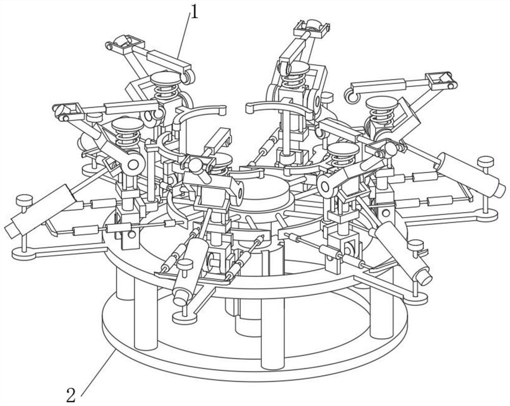
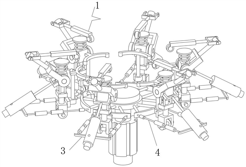
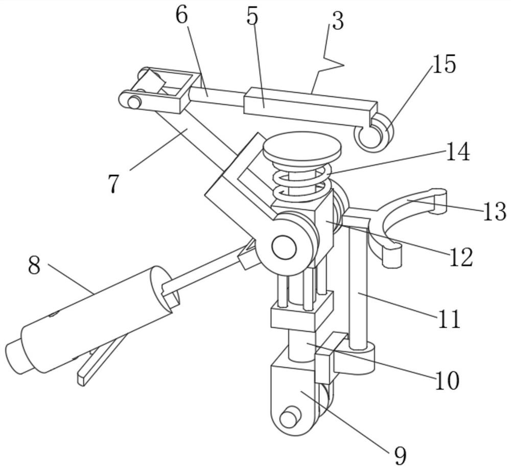
[0030] see Figure 1-6 , the present invention provides a technical solution: a mechanically derived one-piece limiter, including a limiter connection device 1, the lower end of the limiter connection device 1 is hinged with a supporting and stabilizing device 2, by installing the limiter connection device 1, The inner end of the limit connection device 1 is combined with the contact part 3 and the linkage part 4. The contact part 3 can help to carry out the s...


PUM


Abstract

The invention discloses a mechanical pushing and guiding integrated limiting device. The mechanical pushing and guiding integrated limiting device comprises a limiting connecting device, a supporting and stabilizing device is hinged to the lower end of the limiting connecting device, the limiting connecting device comprises a contact part and a linkage part, and the linkage part is arranged in the center of the inner end of the limiting connecting device. The side end of the linkage part is slidably connected with the contact part, the contact part comprises an ejector rod frame, a communicating hinge rod, a contact hinge rod, a pushing structure, a bottom hinge plate, a limiting rod, a stand column frame, a sliding block, a connecting arc frame, a spring and a contact wheel, the bottom hinge plate is arranged at the bottom of the inner end of the contact part, and the limiting rod is fixedly connected to the upper end of the bottom hinge plate; the upper end of the limiting rod is slidably connected with the sliding block, and the top end of the sliding block is elastically connected with the spring. According to the mechanical pushing and guiding integrated limiting device, the purpose of limiting and connecting the inner end is achieved through arrangement of the limiting connecting device.

Description

technical field [0001] The invention relates to the technical field of mechanical equipment, in particular to a mechanical derivation one-piece limit device. Background technique [0002] According to Chinese Patent No. CN201720747590.3, the utility model discloses a clamping device and testing equipment with the clamping device. The clamping device includes: a platform and two clamps; the two clamps are arranged on the platform at intervals, and each clamp includes The base body and the pressing plate; the base body is provided with a first clamping groove; the pressing plate is arranged on the base body in a liftable manner; wherein, the first clamping groove of each clamp and the pressing plate jointly define a clamping notch , when the clamping device clamps the shaft, the shaft is clamped in the clamping slots of the two clamps. The clamping device proposed by the utility model can be used to strengthen shafts of different sizes through the structural design of the pre...

Claims


Application Information

Patent Timeline
Patent Type & Authority Applications(China)
IPC IPC(8): B25B11/00
CPCB25B11/00
Inventor 赵婉玉
Owner 东阳市维创工业产品设计有限公司
Why Eureka
Try Eureka