Rotating shaft fixing structure for rear seat of passenger car

A technology of rear seat and fixed structure, which is applied in the direction of vehicle seat, upper structure, upper structure sub-assembly, etc., can solve the problems of high cost, low safety, complex structure, etc.

Inactive Publication Date: 2021-08-20
FAW CAR CO LTD
View PDF9 Cites 0 Cited by
  • Summary
  • Abstract
  • Description
  • Claims
  • Application Information

AI Technical Summary

Problems solved by technology

[0006] The purpose of the present invention is to provide a rear seat rotating shaft fixing structure of a passenger car to s

Method used


Image

  • Rotating shaft fixing structure for rear seat of passenger car
  • Rotating shaft fixing structure for rear seat of passenger car
  • Rotating shaft fixing structure for rear seat of passenger car

Examples


Embodiment Construction

[0024] The present invention will be further described below in conjunction with embodiment:

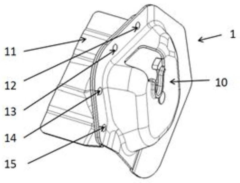
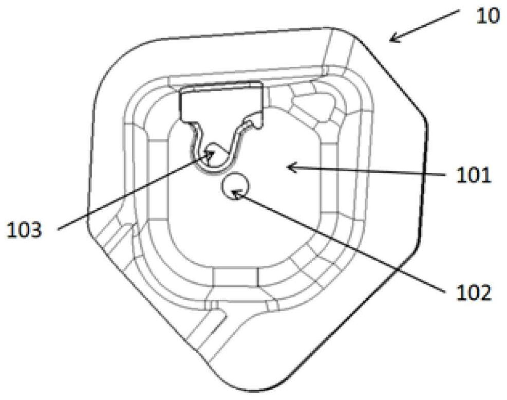
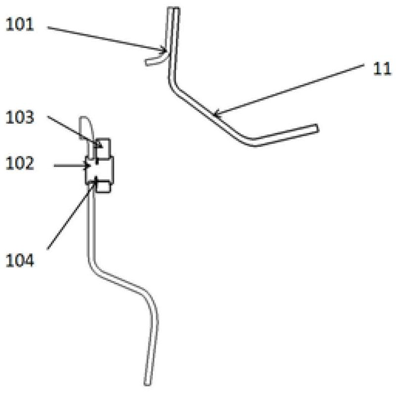
[0025] The present invention will be further described in detail below in conjunction with the accompanying drawings and embodiments. It should be understood that the specific embodiments described here are only used to explain the present invention, but not to limit the present invention. In addition, it should be noted that, for the convenience of description, only some structures related to the present invention are shown in the drawings but not all structures.

[0026] It should be noted that like numerals and letters denote similar items in the following figures, therefore, once an item is defined in one figure, it does not require further definition and explanation in subsequent figures. Meanwhile, in the description of the present invention, the terms "first", "second", etc. are only used to distinguish descriptions, and cannot be understood as indicating or implying relative...


PUM


Abstract

The invention relates to a passenger car rear-row seat rotating shaft fixing structure. The structure comprises a seat rotating shaft fixing hinge plate assembly and a car body rear wheel cover. The vehicle body rear wheel cover provides a welding plane and is connected with the seat rotating shaft fixing hinge plate assembly in a spot welding mode, and a seat rotating shaft is fixed to a vehicle body. The seat rotating shaft fixing hinge plate assembly comprises a fixing hinge plate assembly and a hinge reinforcing plate connected with the fixing hinge plate assembly in a spot welding mode. The fixing hinge plate assembly comprises a mounting shell and a lock hook; a U-shaped opening is formed in the mounting shell and is used for mounting and fixing a seat rotating shaft; and the lock hook can rotate and is matched with the mounting shell. The passenger car rear seat rotating shaft fixing structure has the advantages that the structure is simple, seat installation is more convenient and more efficient, the strength is high, and seat fixing is firmer. Requirements on a vehicle body rear wheel cover in an installation environment are low, the generalization rate is high, and a more positive effect on cost optimization is achieved.

Description

technical field [0001] The invention belongs to the technical field of car seats, and in particular relates to a rear seat rotating shaft fixing structure of a passenger car. Background technique [0002] The existing rear seat shaft fixing structure is mainly considered to be easy to install and disassemble, its relative strength is weak, the shaft is easy to separate from the body, and the safety performance is reduced. In addition, most of the existing rear seat rotating shaft fixing structures are in one form for one model, and the generalization rate is low. [0003] The prior art discloses a seat shaft installation structure comprising: a first bracket and a second bracket, the first bracket and the second bracket are provided with mutually opposite shaft support parts, and the first bracket is also provided with a first welding process hole, the second bracket is provided with a second welding process hole; and a bracket connecting plate, the bracket connecting plate...

Claims


Application Information

Patent Timeline
IPC IPC(8): B60N2/005B62D25/16
CPCB60N2/005B62D25/16
Inventor 李玉杨文斌倪刚孙治东甄丽范凯
Owner FAW CAR CO LTD
Why Eureka
Try Eureka