An automatic smoke extinguisher for new energy vehicles

A technology of new energy vehicles and smoke extinguishers, which is applied in the fields of tobacco, applications, vehicle parts, etc., can solve the problems of pungent, small space, etc., and achieve the effects of avoiding waste, saving water resources, and high practical value

Active Publication Date: 2022-03-11
徐州华祥新能源科技有限公司
View PDF9 Cites 0 Cited by
  • Summary
  • Abstract
  • Description
  • Claims
  • Application Information

AI Technical Summary

Problems solved by technology

[0006] In order to make up for the deficiencies in the prior art, because the space inside the car is relatively narrow, after storing more cigarette ends and soot in the smoke extinguisher, when it is opened again, the peculiar smell in it will float into the car again, giving people a kind of irritating smoke extinguisher. To solve the problem of nasal sensation, the present invention proposes an automatic smoke extinguisher for new energy vehicles

Method used


Image

  • An automatic smoke extinguisher for new energy vehicles
  • An automatic smoke extinguisher for new energy vehicles
  • An automatic smoke extinguisher for new energy vehicles

Examples


Embodiment 1

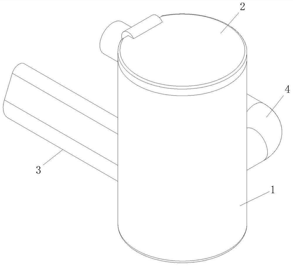
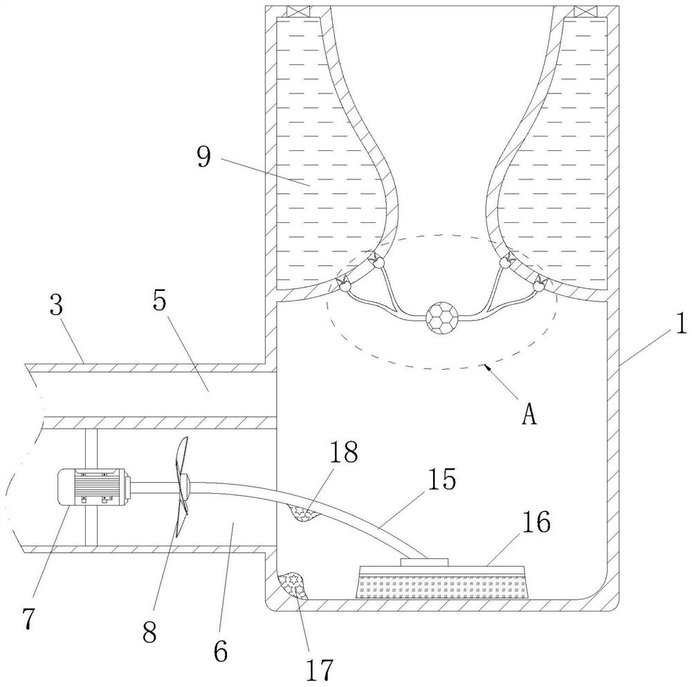
[0031] like Figure 1 to Figure 6 As shown, an automatic smoke extinguisher for a new energy vehicle according to the present invention includes a housing 1, and the housing 1 is installed on the inner surface of the car door; the upper side of the housing 1 is rotatably connected with a sealing cover 2; A ventilation pipe 3 and a slag discharge pipe 4 are fixedly connected to the outer wall of the housing 1, and both the ventilation pipe 3 and the slag discharge pipe 4 are connected to the housing 1; the ventilation pipe 3 is provided with an air inlet groove 5 and an air outlet Groove 6; a motor 7 is fixedly connected to the air outlet groove 6 through a bracket; a wind wheel 8 is fixedly connected to the output shaft of the motor 7; when in use, open the sealing cover 2 of the smoke extinguisher, and throw the cigarette end into the casing 1 and close the sealing cover 2, and start the motor 7 to drive the wind wheel 8 to rotate, and then discharge the smoke in the casing 1...

Embodiment 2

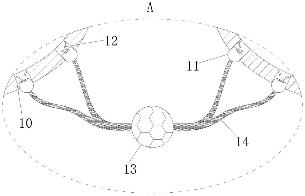
[0041] like Figure 7 As shown in Comparative Example 1, as another embodiment of the present invention, the small ball 13 is rotatably connected with a ball shaft 19, and the two ends of the ball shaft 19 are affixed to the elastic rope 14; the small ball 13 Blades 20 are evenly distributed on the upper circumference; when cigarette butts fall from the top of the housing 1, they will hit the blades 20, and then drive the ball 13 to rotate around the ball shaft 19. Blow to the air intake groove 5, and finally discharge out of the car through the air outlet groove 6, avoiding the problem that the smoke below the water tank 9 remains in the corner and is difficult to remove.

[0042] When working or in use, open the sealing cover 2 of the smoke extinguisher, throw the cigarette butts into the housing 1 and close the sealing cover 2, start the motor 7 to drive the wind wheel 8 to rotate, and then the smoke in the housing 1 will pass through the outlet Groove 6 is discharged outs...


PUM


Abstract

The invention belongs to the technical field of environmental protection equipment, and specifically relates to an automatic smoke extinguisher for new energy vehicles, which includes a housing, and the housing is installed on the inner surface of the vehicle door; the upper side of the housing is rotatably connected with a sealing cover; A ventilation pipe and a slag discharge pipe are fixedly connected to the outer wall of the casing, and both the ventilation pipe and the slag discharge pipe are connected with the casing; the ventilation pipe is provided with an air inlet groove and an air outlet groove; The bracket is fixed with a motor; the output shaft of the motor is fixed with a wind wheel; when in use, open the sealing cover of the smoke extinguisher, throw the cigarette end into the casing and close the sealing cover, and start the motor to drive the wind wheel to rotate. Further, the smoke in the casing is discharged out of the car through the air outlet groove, so as to prevent the peculiar smell in the casing from floating into the car again when the sealing cover is opened next time, causing a pungent feeling to people, which has high practical value.

Description

technical field [0001] The invention belongs to the technical field of environmental protection equipment, in particular to an automatic smoke extinguisher for new energy vehicles. Background technique [0002] At present, some cars on the market are equipped with vehicle-mounted smoke extinguishers to provide users with automatic smoke extinguishing services, which is very convenient and practical. [0003] There are also some technical solutions for vehicle-mounted smoke extinguishers in the prior art. For example, a Chinese patent with application number 2014800074696 discloses an extinguisher for smoking articles, including an outer container, an inner sleeve, an opening, and a cover; The opening is sized to receive a single smoking article into the inner sleeve; the inner sleeve is located within the outer container and is at least partially separated from the outer container; the inner sleeve includes at least one aperture allowing communication between the inner sleev...

Claims


Application Information

Patent Timeline
Patent Type & Authority Patents(China)
IPC IPC(8): A24F19/14A24F19/00B60N3/08B08B1/00
CPCA24F19/145A24F19/0085B60N3/083B08B1/002
Inventor 侯敏
Owner 徐州华祥新能源科技有限公司
Why Eureka
Try Eureka