
Device and method for producing concrete member

A production device and concrete technology, applied in auxiliary molding equipment, ceramic molding machines, mechanical equipment, etc., can solve the problems of easy generation of air bubbles, trouble, affecting the strength and quality of concrete components, and achieve the effect of rapid size and size adjustment

Pending Publication Date: 2021-08-24
安徽瑞澳混凝土有限公司
View PDF9 Cites 0 Cited by
  • Summary
  • Abstract
  • Description
  • Claims
  • Application Information

AI Technical Summary

Problems solved by technology

[0003] The prior art has the following deficiencies: the existing device for producing concrete components is inconvenient and accurate to put steel bars in. When adjusting the size of the concrete components, manual reconstruction is required, which is cumbersome, time-consuming and laborious, and after pouring concrete raw materials, the outer surface is not very smooth. It is also easy to produce air bubbles, which can easily affect the strength and quality of concrete components

Method used


Image

  • Device and method for producing concrete member
  • Device and method for producing concrete member
  • Device and method for producing concrete member

Examples


Embodiment 1

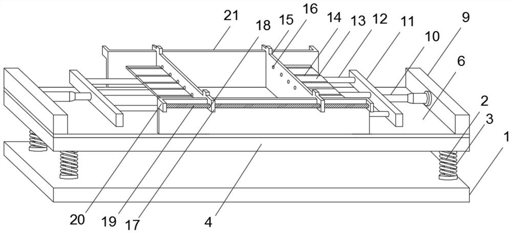
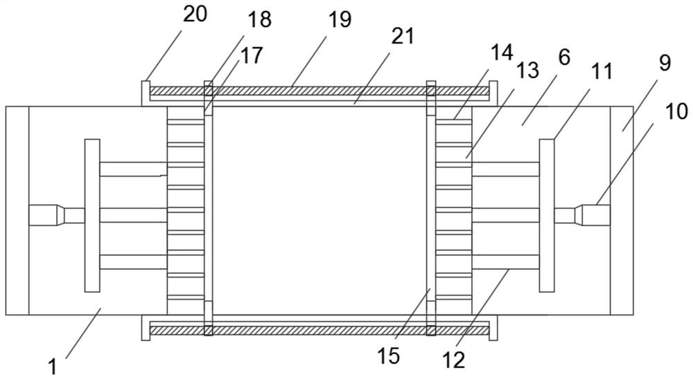
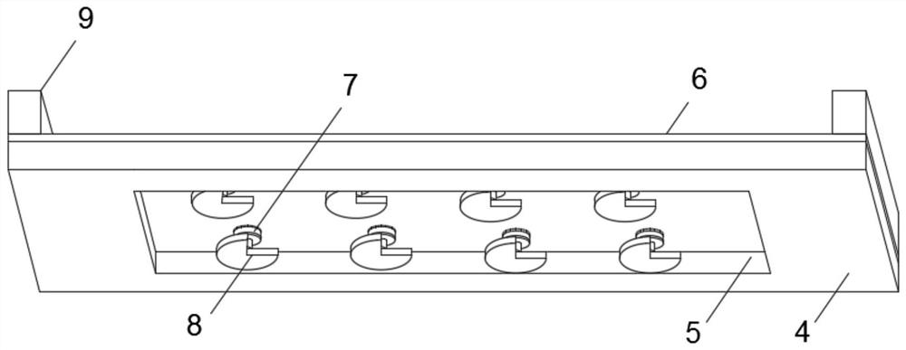
[0039] Refer to attached Figure 1-Figure 7 , a device and a production method for producing concrete components in this embodiment, comprising a production device body one 1, a load-bearing platform 4, a forming bottom plate 6, a forming side plate 21, an adjusting plate 15, a steel bar load-bearing plate 13 and a production device body two 32 The outer surface of the top of the load-bearing platform 4 is provided with a square groove 5, the top of the load-bearing platform 4 is provided with a forming base plate 6, the bottom of the forming base plate 6 is installed with a servo motor 7, the output end of the servo motor 7 is fixedly connected to the eccentric wheel 8, and the top of the forming base plate 6 is installed with a side Plate 9, one side of side plate 9 is fixedly connected with hydraulic cylinder 10, and the output end of hydraulic cylinder 10 is equipped with moving plate 11, and one side of moving plate 11 is fixedly connected with moving rod 12, and one end o...

Embodiment 2

[0049] Refer to attached Figure 8 , a device and production method for producing concrete components in this embodiment, including a production device body 2 32, a reduction motor 29, an internally threaded rod 30 and an externally threaded rod 31, specifically, the production device body 2 32 includes a side plate 9, A reduction motor 29 is installed on one side of the side plate 9, the output end of the reduction motor 29 is fixedly connected to the internal threaded rod 30, and one end of the internal threaded rod 30 is sleeved with an external threaded rod 31, and the external threaded rod 31 is fixedly connected to the adjustment plate 15, and the reduction motor is activated by starting the reduction motor. 29 drives the internally threaded rod 30, drives the externally threaded rod 31 to extend outward, and drives the adjusting plate 15 to slide, so as to quickly adjust the size of the concrete member.

[0050] The use process of the present invention is as follows: wh...


PUM


Abstract

The invention discloses a device and method for producing a concrete member, and particularly relates to the technical field of concrete member machining. The technical scheme is that the device comprises a production device body I, a bearing table, a forming bottom plate, a forming side plate, an adjusting plate, a steel bar bearing plate and a production device body II; a square groove is arranged on the outer surface of the top of the bearing table; the forming bottom plate is arranged at the top of the bearing table; a servo motor is installed at the bottom of the forming bottom plate; an output end of the servo motor is fixedly connected with an eccentric wheel; the side plate is installed at the top of the forming bottom plate; and one side of the side plate is fixedly connected with a hydraulic cylinder. The device has the following beneficial effects: steel bars can be conveniently and accurately placed, when the size of the concrete member is adjusted, time and labor are saved, and after concrete raw materials are poured, internal bubbles can be removed, the surface flatness of the concrete raw materials is improved, and the strength and quality of the concrete member are improved.

Description

technical field [0001] The invention relates to the technical field, in particular to a device and a production method for producing concrete components. Background technique [0002] Cast-in-place concrete components mainly refer to beams, slabs, columns, stairs, foundations, etc. The cast-in-place concrete components are mainly different from prefabricated concrete components, which are concrete components that are poured and formed on the construction site. Taking a project as an example, starting from the underground foundation, The cast-in-place concrete part includes the foundation floor, columns, floor slabs, beams, stairs, etc., and there are structural columns and ring beams during the secondary structure. At the same time, concrete also has the characteristics of high compressive strength, good durability, and a wide range of strength grades. These characteristics make it widely used. It is not only used in various civil engineering, but also in shipbuilding, machi...

Claims


Application Information

Patent Timeline
IPC IPC(8): B28B23/02B28B1/087B28B17/00F16F15/067
CPCB28B23/02B28B1/087B28B17/00F16F15/067
Inventor 芮傲年
Owner 安徽瑞澳混凝土有限公司
Learn More